


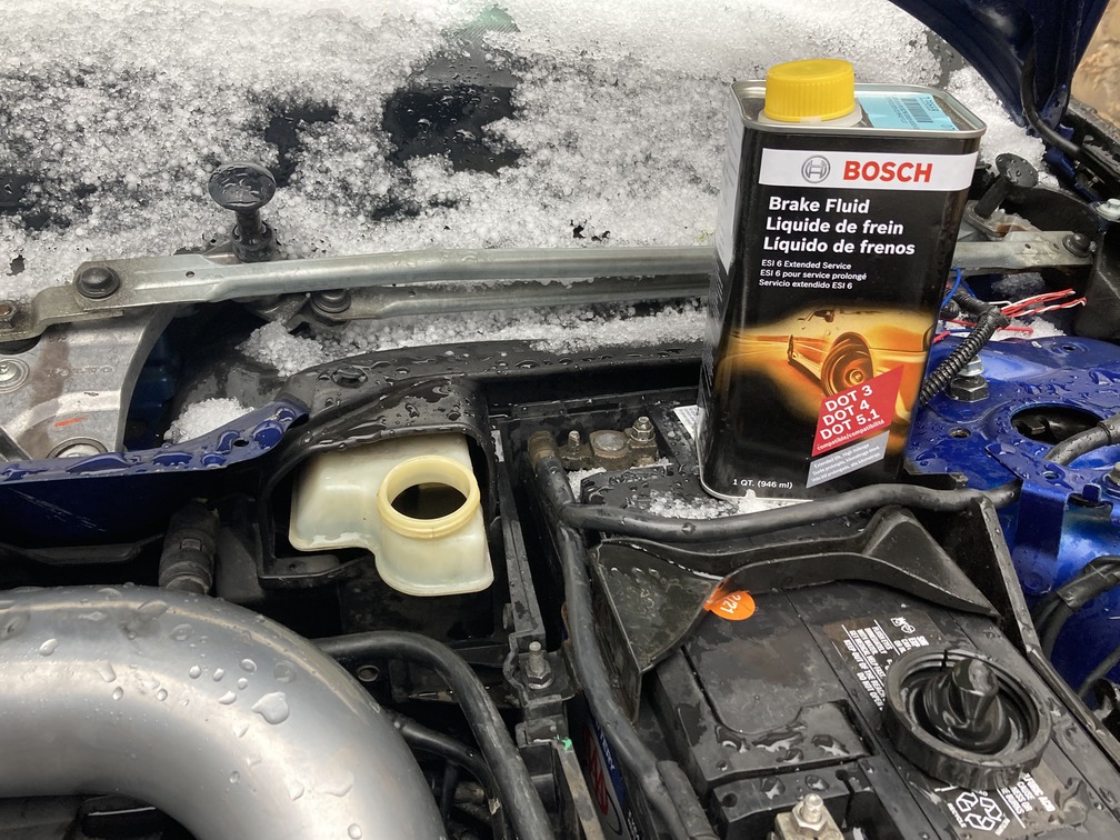
THE SWAP IS COMPLETE as of May 2nd, 2022
Shout out to IPD – The Volvo Parts, Accessories & Performance Specialists Since 1963, for their awesome support on this project, as well as getting all the parts we needed to us quick…

Okay guys and gals, so there has been a lot of talk about why you can’t, or why you shouldn’t do this swap, but since we are already financially committed to doing the swap, I figured I would do the research, and make this guide for everyone else out there with the questions, and the ambition to knock it out.
This article will be a living update as the process evolves, but for starters we think we have most of what we…. and you will need. We welcome anyone to add in any thoughts or information we’re missing here, and we will update this original article to make sure we always have the most up to date and accurate information.
We just finished the parts sourcing phase, and all at local junkyards and via donor cars, so we should be ready to start the actual conversion mid 2021.
Why You Can’t or Shouldn’t Do This Swap
For starters, here are the reasons that everyone on the forums were saying that you should not, or can not complete this swap:
- Cost too much money.
- Cheaper to buy a stock M66/M56 car.
- ECU/computers will not work after swap.
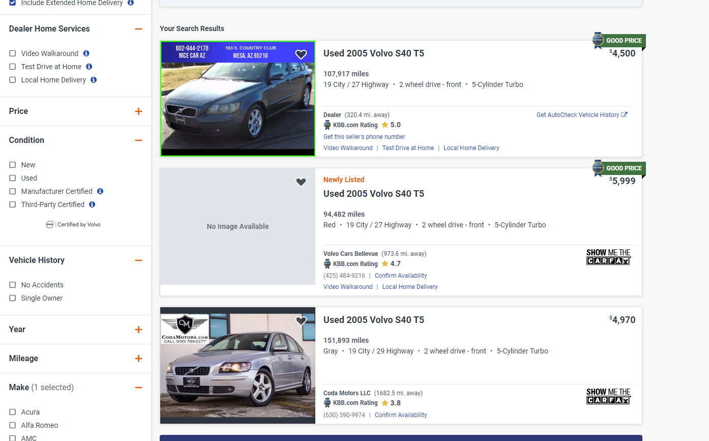
While it is true that it may be cheaper to buy a factory manual, at any given time on Autotrader, there are less than a handful nationwide ever available, most with high miles and for many of us who have put blood, sweat and tears into our car, we simply love ours too much to go this route. I did a quick search on AutoTrader for any distance (nationwide USA), S40s with a manual…only 3 results in the entire US. Then I added AWD filter and NONE.
Also, for many of us (me included) you cannot find a replacement car with the options configurations you currently have, meaning you are trading out many options for a manual. We cannot live with “either or”, but rather opting for “ALL”. This includes a rare color code (476), AWD T5, with every factory option installed (climate package, premium sound, factory AUX, sliding sunroof, black leather and more….).
For the last rebuttal of computer systems not working….that has been solved with Hilton Tuning successfully converting your current ECM and CEM to work as a manual.
Forum Chatter – Consolidated
Next, here are a few of the major threads around this topic (went looking to combine anything useful and save others time of hunting):
– A successful swap on a c30 here: Reached out and talked to levolvolagt, and I confirmed with him over a lengthy chat on Insta.
Someone selling the components you need for the swap here, showing that people are thinking about it, and compiling parts to execute it.
Successful swap with advanced wiring (reverse lights, reverse lockout, clutch position sensor) on an R. While different platform, it shows the process for tracking down and completing the final wiring portion. Also in Mvl_S60R‘s thread he links out to some other useful information here and here.
Then a a few threads on people asking the question….with no real answers or information: here, here and here.
And finally the threads just saying it is possible with enough money: here and here.
Which is a perfect lead in to costs overview.
What Will It Cost?
There are 2 ways to go about this and a few variables each way. They are just some parts you have to buy new, and some you can decide if you want to upgrade in the process and many parts you can source used. Essentially it breaks down like this, but anyone can mix and match for their own swap.
$10,582.00: This is every part number you need, and buying it brand new from Volvo dealership parts department. Wanted to lay out the high end of the swap…and obviously at this price it isn’t an option…unless you got mad funds.
or
~$2500.00: Sourcing re-usable parts used from junkyard/ebay/donor.
Here are the expensive things that are factored into both breakdowns:
New flywheel: $500-1000
New Clutch: $300-600
Transmission: $150 junkyard, $650 LKQ shipped or $4400 dealer 0 miles.
Software: $825
Also to consider in price, if you have a tune on the car, it may not work after the software conversion to manual. Don at elevate said his should load right up onto the Hilton conversion after. Hilton said other tunes may not work after. Here we will try to load the Elevate tune on the Hilton conversion software, and worst case we lose a tune, and gain a 6 speed. At that point we know we may have to look at a Hilton tune or a modified Elevate tune. This is a big if, as purchasing a new tune could run $300-$900…. more!
Required Parts with Part Numbers
So for this section, we made a master spreadsheet with all the parts we could think of for our 2006 T5 AWD. From there we searched the Volvo parts webstore and noted all parts and part numbers. Then we expanded the search to USDM S40s of the same year, which included the 2.4 FWD Auto, 2.4 FWD Manual (M56), T5 Auto AWD, T5 Auto FWD, T5 manual AWD and T5 manual FWD. Then we went down the list and cross referenced all parts against the webstore. This was because we were confirming which parts were different, and which parts would possibly be used again, and more importantly, which cars would be donors we could grab parts from at the junkyard.
Then we decided why not expand my list of donor cars, as well as make our research benefit all 2005-2012 Volvo S40s and V50s (We didn’t expand to C70 or C30 but for the most part they will be the same too). From there we then cross referenced and checked all the same above 6 USDM powertrains across 6 years (2010 was the last factory manuals per Volvo parts website). That worked out to be 85+ parts X 6 power trains X 6 model years….that’s over 3,000 parts we checked…all to realize that they are pretty much the same across the P1 platform for the entire 6 years. Their are variations, which was why we checked them all. Certain donor parts will need to be from certain donor cars, and part numbers may also be chassis/VIN specific.
So here we are, and again, if we missed anything, please let us know and we will cross reference and add to the article for everyone. Further, this is the complete list, but below in our parts section, we have a quick reference shopping list for the parts you need to actually buy new.
Pedals:
Brake Pedal (All years and engines): 31341384
Gas Pedal (All years and engines): 31445344
Clutch Pedal:31317868 (CH 74719-.) 2.4 and T5, 31341443 (CH 63833-. DSL, 4CYL, L.H.D.) 2.4 and T5 and 31317872 T5 only.
Clutch Master Cylinder: 31367403 and 31367404 for 2.4 and then for T5:31367404
Spring Kit 2.4:31200941 and 31200238 (CH -135505. CH -452602. CH -453119. CH -472317. CH -473361. CH -74718. CH 17951-135153. CH 304267-. CH 320804-. DSL, 4CYL, L.H.D. DSL, 4CYL, R.H.D.)
Spring Kit T5: 31200942: CH -72770. CH -63833. CH -396178. CH -380303. and 31200239 for CH 72771-. CH 63834-. CH 63833-. CH 396179-. CH 380304-.
Clutch – 2.4 FWD
Clutch & Pressure Plate: 30711578
Clutch Line (pedal to tranny):30759391
Air Vent Pipe:30787651
Bleeder Nipple: 8675509
Bleeder Nipple Cap 656456
Suction Hose (clutch pedal to reservoir)30614449
Clutch Pipe 30759394
Quick Coupling (Clutch Pipe to Clutch Line)(Dicsont)9181729
Throw-out bearing/slave cylinder (Gearbox section)8675052
Clutch – T5 FWD and AWD
Clutch & Pressure Plate: 30783253 (-4248477) and 31367641 (424847 Clutch Line (pedal to tranny)31256074
Air Vent Pipe30787651
Bleeder Nipple: N/A
Bleeder Nipple Cap: N/A
Suction Hose (clutch pedal to reservoir)30614449
Clutch Pipe30759394
Quick Coupling (Clutch Pipe to Clutch Line) (Dicsont)9181729
Throw-out bearing/slave cylinder (Gearbox section)31258380
Axels: Listed Auto and Manual to show there are very specific part numbers, that do not match others. They are year and model specific.
2.4 Auto
CV Axel Right: 36000559
CV Axel Left36000550
2.4 Manual
CV Axel Right: 36000559 for 2005-2006 and 2007-2010 is 36000555.
CV Axel Left: 36000546
T5 Auto FWD
CV Axel Right: 36000559
CV Axel Left: 36000550
T5 Auto AWD
CV Axel Right: 36000561: CH -472491. CH -452736 or 36002670: CH 472492-. CH 452737-.
CV Axel Left: 36000551: and 36011266: EXCH FOR 31367540, 31280679, 31280683. EXCH FOR 31280679, 31280683.
T5 Manual FWD
CV Axel Right: 36000555
CV Axel Left36000546
T5 Manual AWD
CV Axel Right: 36000556: CH -452736. CH -472491 or 36002669: CH 452737-. CH 472492-.
CV Axel Left>36000547
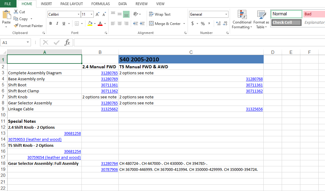
Shift Knob, Boot, Gear Selector and Related….2.4 M56 and T5 M66 are almost all different in this section.
2.4 M56
Complete Assembly Diagram: 31280765
Base Assembly only: 31280769
Shift Boot: 30711361
Shift Boot Clamp: 30711362
Shift Knob:30681258 (standard) or 30759053 (leather and wood).
Gear Selector Assembly: 31280765
Linkage Cable: 31325662
T5 M66
Complete Assembly Diagram
Base Assembly only: 31280768
Shift Boot30711361
Shift Boot Clamp30711362
Shift Knob:30681254 regular or 30759054 (leather and wood)
Gear Selector Assembly: 31280764 (CH 480724-. CH 447000-. CH 430000-. CH 394785-).30787906 (CH 367000-446999. CH 367000-413994. CH 350000-429999. CH 350000-394724.)
Linkage Cable31325656
Engine Bay Parts
Flywheel bolts: 9454743
Flywheel 2.4 FWD: 31259331
Flywheel T5 FWD & AWD: 313254102 part or 31325792 or 31259452 2 part
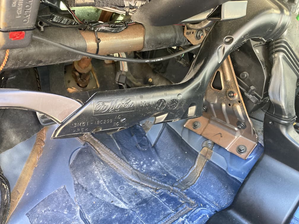
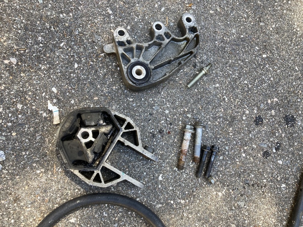
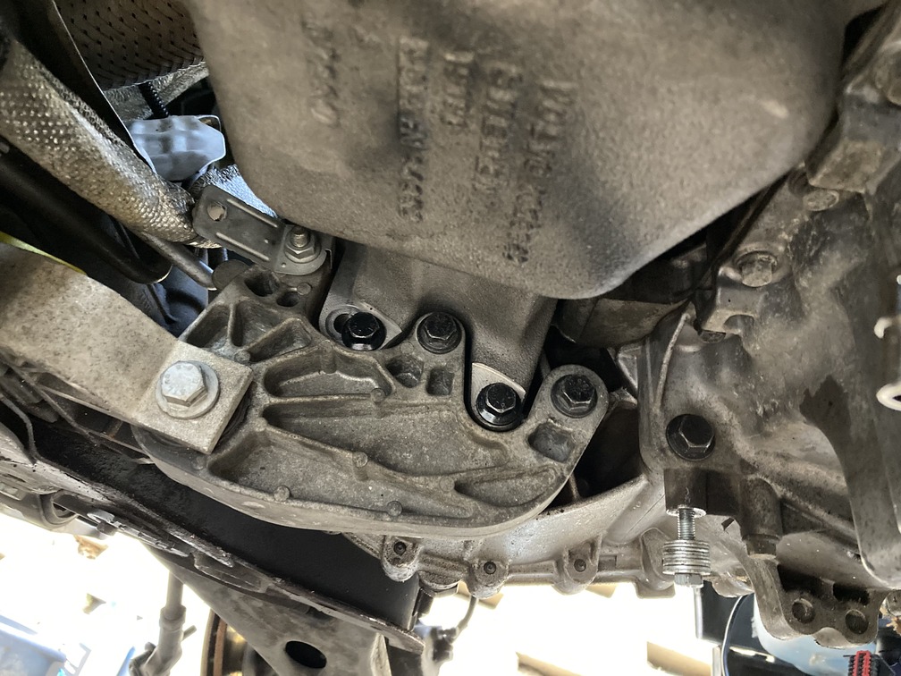
ENGINE MOUNT BRACKET (#12 in pic)
2.4 Auto Trans: 30680782 CH -194443. CH -190210 or 30778794CH 194444-. CH 190211-.
2.4 Manual: 30680783M56. CH -194443. CH -190210 or 30793552M56. CH 194444-. CH 190211-.
T5 Manual FWD & AWD: 30680784 or CH -194443. CH -190210. M66. M66 AWD.30778793CH 194444-. CH 190211-. M66. M66 AWD.
T5 Auto: 30680782 CH -194443. CH -190210 or 30778794 CH 194444-. CH 190211-.
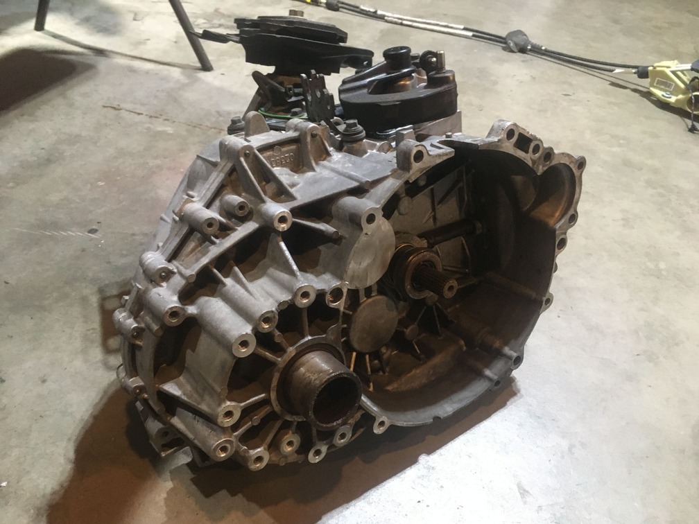
The Transmission (M56 or M66)
Would love some more help here. We know the M66 came in a lot of things, but the part numbers below only cross reference between S40 and V50. Are there other cars we can source these from with small modifications?
Also the main options we see here are brand new from dealer ($4,000), pick yourself at junkyard ($170), LQK online ($500-700), buy from someone on forum, get it in your donor…
2.4 FWD:8252146
T5 M66 FWD: 8252159 & Special Note: CH -236961. CH -541494. CH -616844.
T5 M66 AWD: 8252157
Parts researched that turned out to be the same auto vs manual, so not needed for swap.
Brake Booster, Brake light sensor, Waterfall interior trim, master brake cylinder, crankshaft, angle gear (awd), driveshaft, all other engine mounts, carrier bearings….
As mentioned above, if we am missing anything, let us know and we’ll research and add it to the list.
Sourcing Your Parts
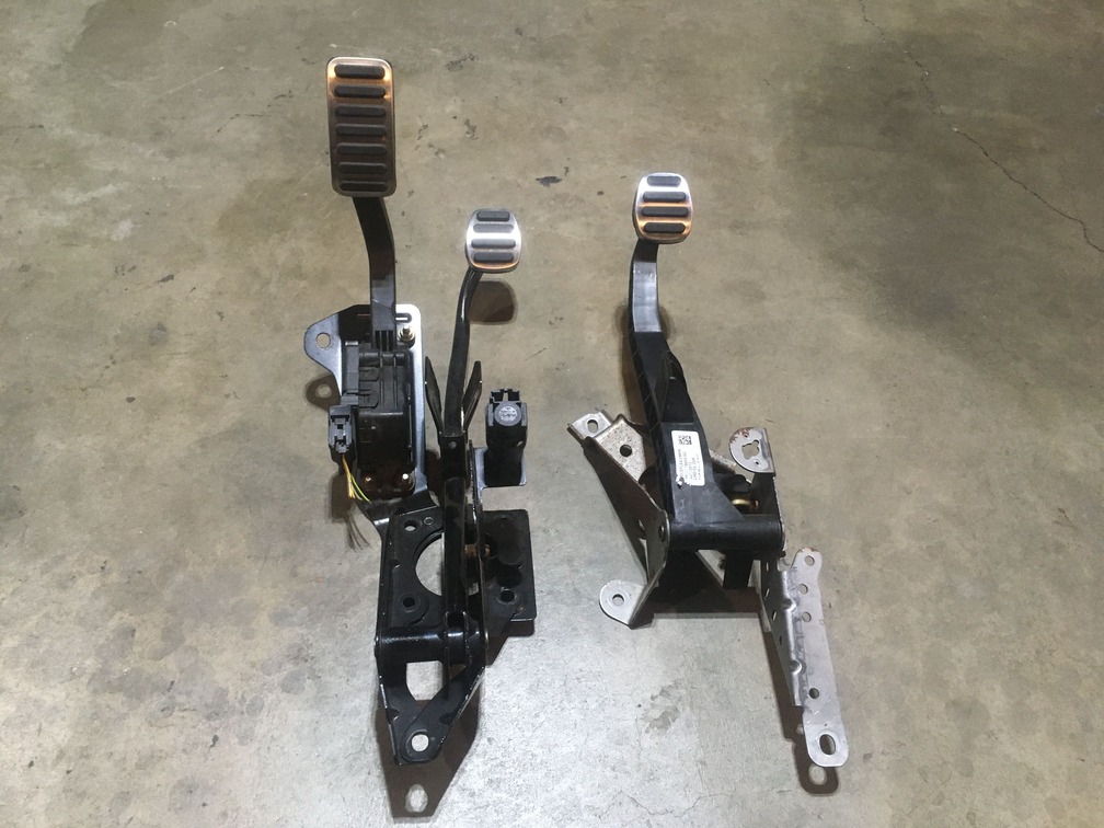
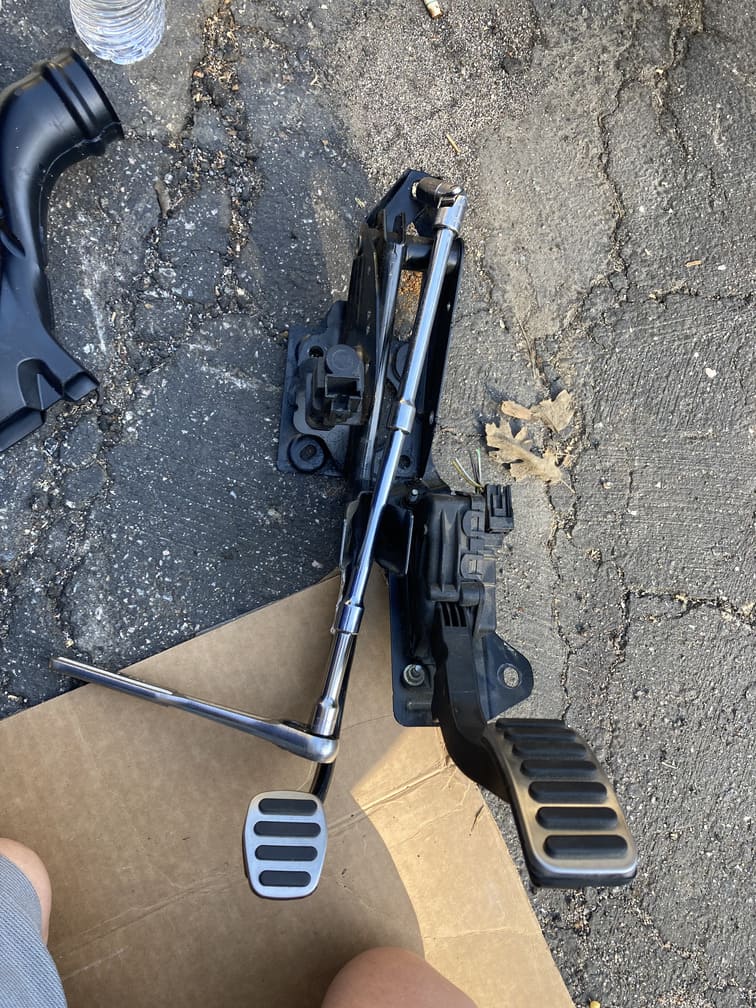
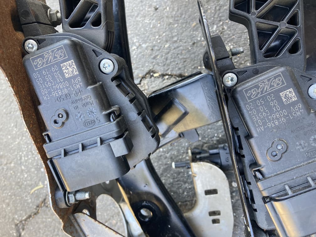
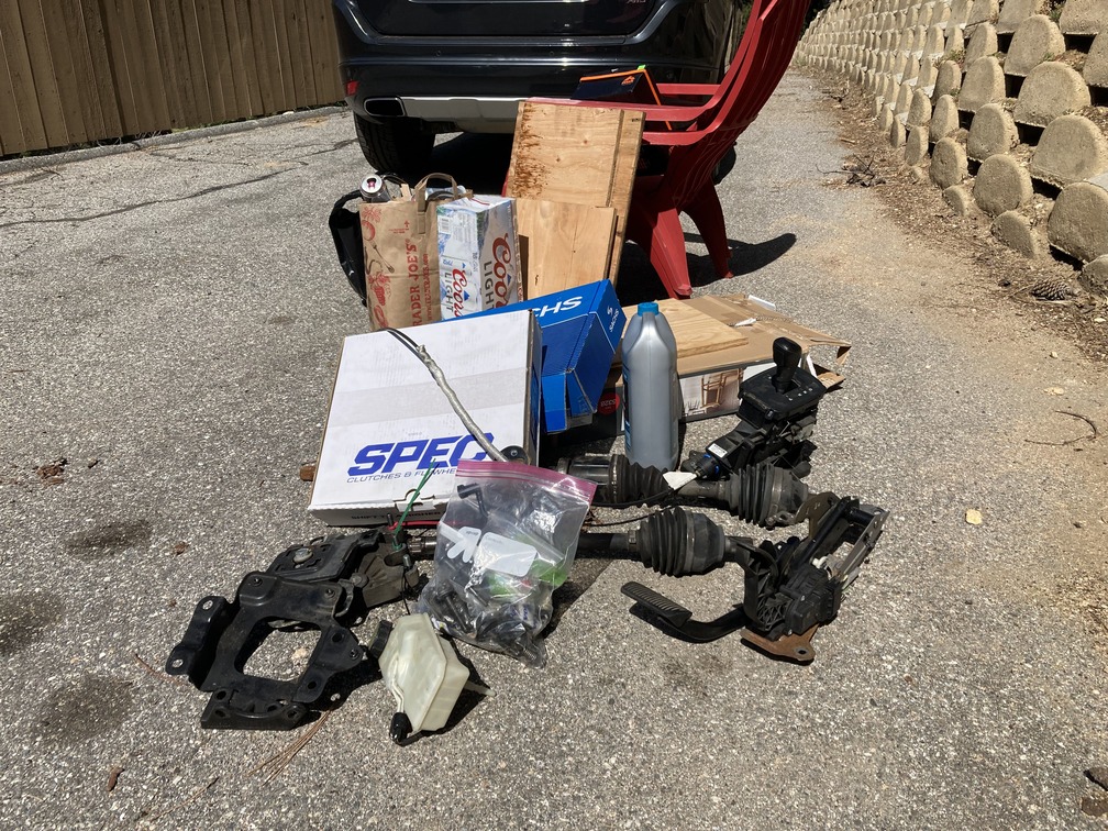
So initially as we were making the above list, we were peeping the junk yard app and went out and had grabbed a few pieces to start the swap. This included shifter assembly, which we later trashed because we hadn’t got that far in research and grabbed a set from a 2.4 which didn’t work for our install. We also spent a few hours ripping the pedal assembly out which is usable.
And then we saw a Facebook notification that a marketplace item we chatted about a year ago dropped in price. This was a guy who had our exact sister car with a M66. Since we have the AWD and T5 application, we can almost only use parts from a AWD T5 M66. His engine blew and he was selling the car as is. Within a few days we were getting this thing towed back tot he garage. $1600 all in. As of today, 5 months later, we have sold $1100 in extra parts on eBay. We did have a few C30 guys interested in the AWD components, but shipping a whole car made it not worth it, so last week we scrapped the donor as we are moving and need it gone.
For most people you are in two categories for sourcing parts. This will be a full donor or part by part online/LKQ/Local yard. Lets explore both:
Sourcing Parts Via Donor: This was by far the easiest way to get the complete parts bundle we didn’t know until we had the donor. As mentioned above, we started the junkyard route, and figured it would take a year or two to complete. The local pick a part no longer sells full cars, so here in Southern California, we couldn’t find a donor and bring it home. Many of you will be pulling these parts one by one at the yard.
I would encourage you all to look weekly at the craigslist, the AutoTrader, the offer up and any other Facebook groups or marketplaces. Many times people will blow an engine, or have a totaled car they will sell you for $1000ish. After I purchased my donor I saw a few more come up in the same condition, for cheaper. So doing it again, I would be looking here all the time and probably get lucky. Further, some of these cars will have high mileage and you may even get one for $2000+, which I would still consider a deal. We made most our money back parting the car out, and still have a few hundred dollars of eBay listings up.
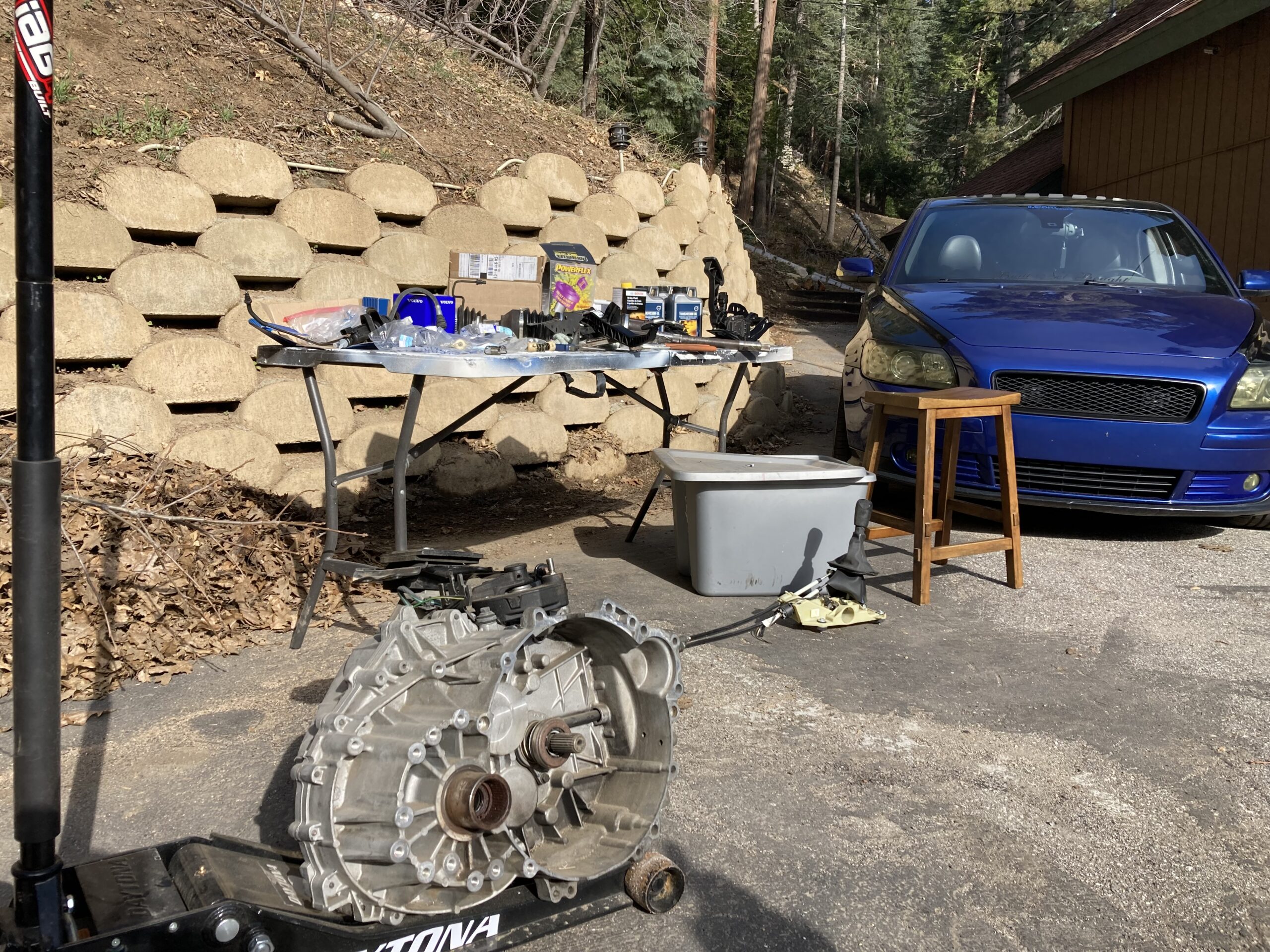
The donor route is also great because you have no time crunch or crazy conditions when trying to get the parts off. With the donor, we were able to put it on stands in the middle of our four car garage. We had air tools, power tools, a flat clean ground, and climate control. It took us a week to fully strip the car. This was what we needed for the swap, and then pulled the rest part by part, and listing each on eBay.
Sourcing Parts Via Junkyard and Used Online: This was again where we started, and so glad we found a donor. After plucking the M66 in a nice controlled environment, we realized how hard it would be to do it at the yard, on the dirt, with the car teetering. This however is if you’re going for the cheapest sourcing of parts. We were also looking at grabbing an M66 from LKQ, which would essentially be delivered to us, and with a warranty if we chose. The yard price for the tranny would be $163, and LKQ was $600-$800. Big difference and we thought for that price we could even go through a few at the local yard if the one we got was bad and still save money.
While the junkyard and online would take longer than a donor, you can still get everything you need, but also may pay more than a straight wrecked donor. If you are going this route, know it will be hunting for the right parts, in the right condition. This also seemed okay to us initially as it would let us spread the swap cost out as long as we wanted it to be.
Grouping Parts Before Installation
As mentioned above, there are some parts you can install used, some you want to buy new, and some you can rebuild. Used parts could include the pedal assembly, the shifter assembly and other parts that don’t ever fail. Parts you would want to buy new, but we won’t judge if you install them, would be the clutch, the flywheel, clutch master cylinder… any part that does fail, and or is a “B” to install. Then those parts you can rebuild such as axels and seals. This is also a good chance to upgrade any parts that are coming off anyways. Lets take a look at the parts in each of these categories.
Parts we are cleaning and using as is:
Pedal Assembly: After cleaning any debris, and then greasing/oiling any moving parts, the pedals are pretty much bulletproof. All the mounting hardware will also be used without upgrade. Here if you notice too much play, you could look at the $44 spring kit. Below we show how we rebuilt the springs on the clutch pedal.
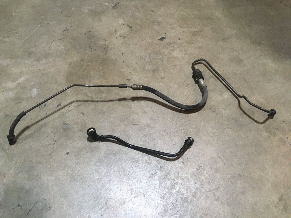
Clutch Hose Lines: There are a few hoses that provide pressure from the clutch pedal to the actual slave cylinder. These are a cross between soft and hard lines and are actually a hard plastic contoured to fish through the bay. These lines are pretty solid, and if not brittle, and the connections are clean and sturdy, re-using should be fine. But upon inspection, if you see any weakness or potential points of failure, move these to your replace category. In our situation we opted to keep the hard line, and get a new plastic line. Our end connections on the plastic one was chewed up so for $40 a new one gives some piece of mind. Part number: 30614449

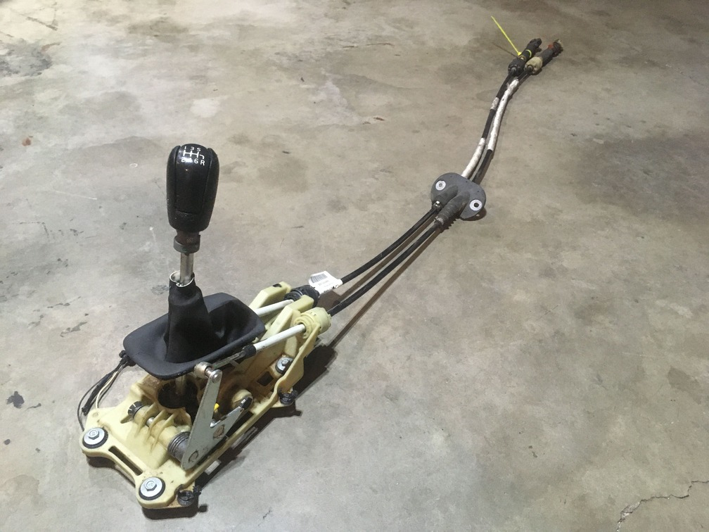
Shift Linkage and related: This section is your gear knob, shift boot, shifter assembly and the cables. These are all inside the interior trim, and should be solid from the donor. A little cleaning of crumbs and spilled soda as well as some greasing should put this whole assembly ready to go. If you do however see any issues with the cables such as wearing, stretching or anything else to give you issue later, you can swap out just the linkage cables cheap enough. Below we show what we did to prep our shifter assembly for installation.
Parts we are rebuilding from the donor: This group of parts are some of the core essentials for the swap. They are however too expensive to buy brand new. If yours are in good shape you could simply install, but to reduce potential issues later, and to know you are putting in maintained core parts we are doing the following:
The transmission: This is the whole reason we are here writing this article, and why you’re reading it. While the M66 are not easily rebuilt…haven’t seen much on that anywhere, there are components you can get to get it more stable. The dang thing is already sitting on the floor so these are quick and easy. We will be replacing all the seals, obviously putting new fluids, and the air vent pipe. Since the vent pipe is inside the tranny/engine mounting, if this brittle plastic breaks or cracks later you are pulling the whole M66 out to replace this $50 part, just do it now.
The Angle Gear: For us AWD bosses, we have this extra part to be concerned about. While the angle gear is exactly the same part from your donor, you will want to decide which one to use. We are using our current since it has dramatically less mileage than our donor car. However, again, the thing is sitting on the floor at the moment, so we are doing the collar gear kit which includes a new collar gear, the seal and the new hardware. We’re grabbing this from IPDUSA.com for a cool $165. Last thing you want is issues sending your new gear ratios to the rear.
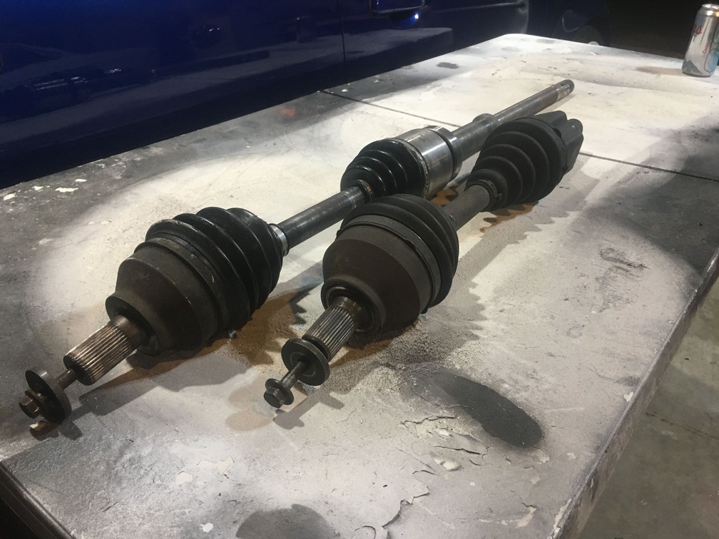
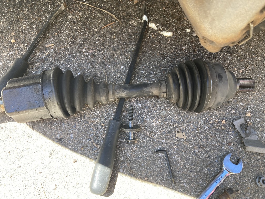
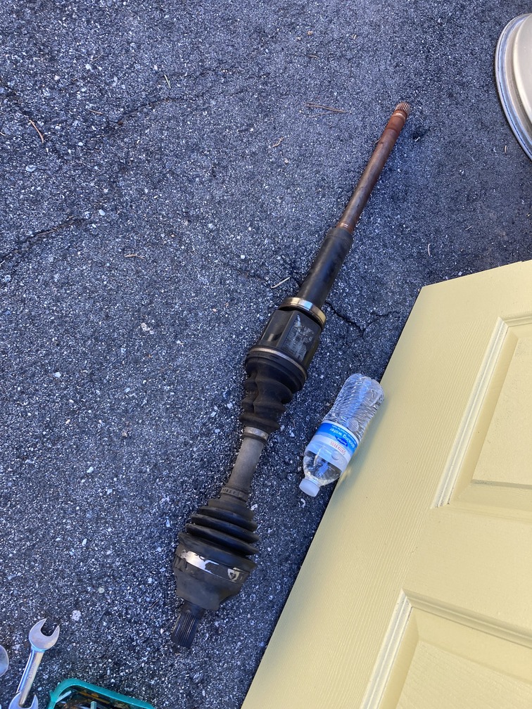
Axels: If you looked at our spreadsheet above, you did see that every single drivetrain variation does use a different axel for both driver and passenger side. Meaning you will be using the axels from the donor car, what you have now is not compatible. If you’ve spent any time on the forums, then you know the original Volvo axels are superior to aftermarket replacements. We’ve seen tons of posts of fitment and quality issues with the cheap replacements, which is maybe why they are like $600+ from Volvo for the factory replacement. Any ways, we went ahead and swooped up the full axel rebuild kits here which includes the new boots, clamps, bolts and grease. We’re going to clean these things up squeaky and after the re-build they should be solid.
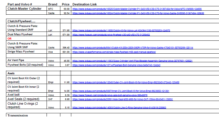
Parts we are buying brand new: There are certain things you simply do not want to re-use. Here we talk about those. These are mainly things you are replacing at interval anyways, and since the whole install is out, it’s the best time to do it. Also, putting these parts in used from your donor would just be irresponsible as you can’t judge if they will last another 30,000 miles, or break into pieces on your first test run. Here we made a quick shopping list using the best option for Volvo parts, IPDUSA. This includes what we discuss below as being things you should replace while you are converting. Shopping list PDF here.
Guys!!!! IPDUSA – That’s Where you need to get your oem/oe replacement parts, no questions asked. Don’t waste your time looking elsewhere.
Performance Parts and Upgrades aside from Stock, check out Viva Performance, who we are using for the SMF upgrade and Elevate who also has a complete kit.
Clutch: Don’t really need an explanation here. Replace it.
Throw out bearing/slave cylinder: This is inside the tranny/engine assembly, so going back later is a waste of time. Also these come in the clutch kit and are cheap enough.
Pressure plate: Subject to warping and waste of time to replace later. These also come in the clutch kit, so just get the bundle and know you’re good to go.
Flywheel: A lot of forum chatter here, but overall the thoughts are that these cannot be re-surfaced. This is one of the more expensive replacement parts, but you’ll be glad you did it. If you did get a low mileage donor (unlikely) then maybe just maybe it would be re-usable. This is also an opportunity to upgrade to something a bit better since it’s already being replaced. Further, either way you should get the flywheel bolts at $4X10. We are doing the single mass flywheel upgrade and sourcing that from Viva Performance, see that part here.
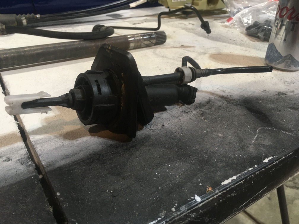
The Master Clutch Cylinder: Found directly on the clutch pedal assembly. Half in the cabin and half in the engine bay. This was by far the hardest part to remove from the donor as the battery and other firewall panels must come off, and and bolts that secure it in are located behind the gauge cluster. Since this operates the entire clutch, and is super hard to remove and replace, and prone to leakage and failure, get a fresh one, they are between $50-150 on IPDUSA.com.
Potential for Upgrade Parts:
This section is optional, but depending on your flavor preference and future mod list, you can knock a few birds out here.
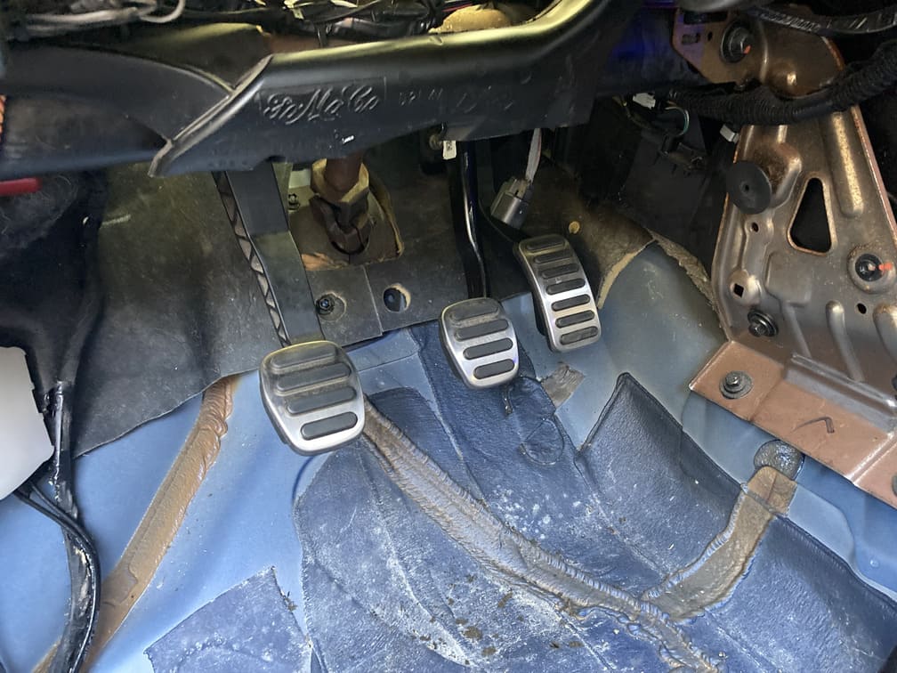
We will be doing an upgraded stylish shift boot and custom shift knob. We also already purchased the R-Design (Sport Pedal Set) pedals for a more sporty and uniform look.
You could look at performance clutch and flywheel. We are going with the S60R clutch kit and the Viva Performance Single Mass Flywheel.
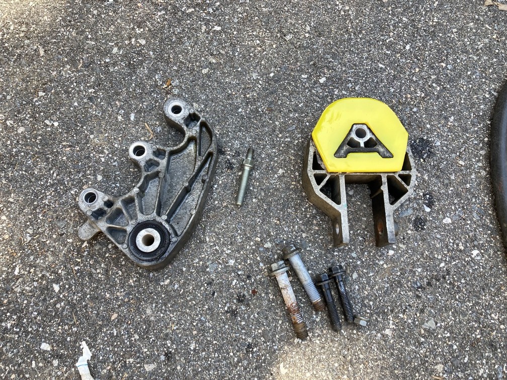
Also the lower torque mount and transmission mount can be swapped out for some poly bushings for some more stability and rigidness on the ride. We are going with these via recommendations of Volvo P1 Guru Michael C. Hallock:
Powerflex Ford Focus Mk2 / Volvo Transmission Mount Insert
and
Ford Focus Mk2, Mk3 / Volvo C30, S40, V50 Lower Engine Mount Insert – Late Type
Let’s Get Started – Prepping the Parts
Axels: We are starting with the parts re-build and first up was the axels. Here we ordered 2 full rebuild kits from IPDUSA.com for both axels at about $65 all in. Inner kit and Outer Kit. We did a full cv-boot replacement and bearing clean and grease here, but you can see the overview on the video here:
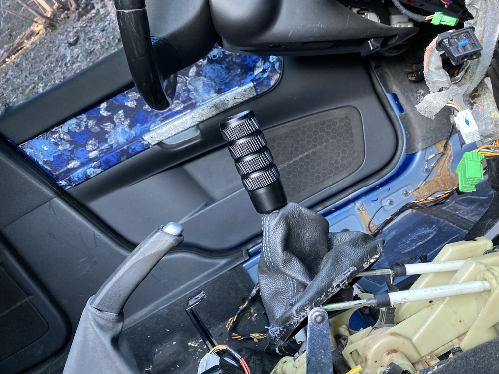
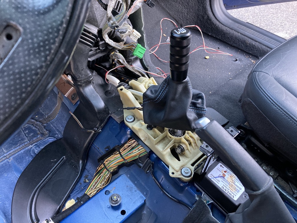
Shifter Assembly: As mentioned above, there isn’t too much to do here. Clean and prep. We however, decided this was a great chance to get rid of the boring factory shift knob and boot, and spice it up a little. We went for the king of all shift knob companies, LIKEWISE.
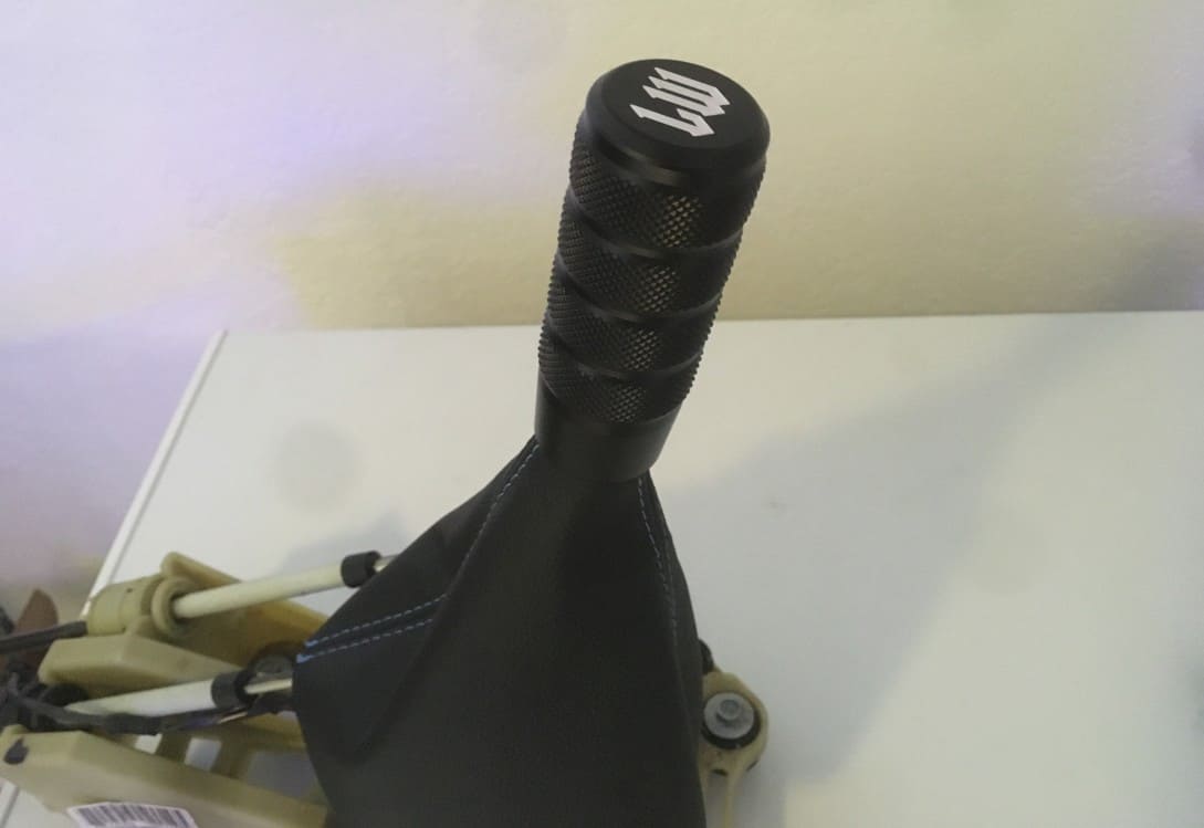
You can see over overview and product review here:
LIKEWISE Shift Knobs & Accessories – One of the Best Out There
Further, here is a quick video on what we had to do to make the shift knob work, and test the shifter assembly before installation.
Pedal Assemblies: Covered above, nothing really to do here. Just make sure they are clean, and the springs have tension and the pedals move freely. We decided that since the pedals were out, and we had no idea how much tension and play was normal, that we would replace the 2 springs on the clutch pedal assembly, ordering part #31200942 from Volvo. Be careful, as part number 31200941 may also show as compatible, but we found it not to be after ordering and trying to install it. You can see our quick video on that installation here:
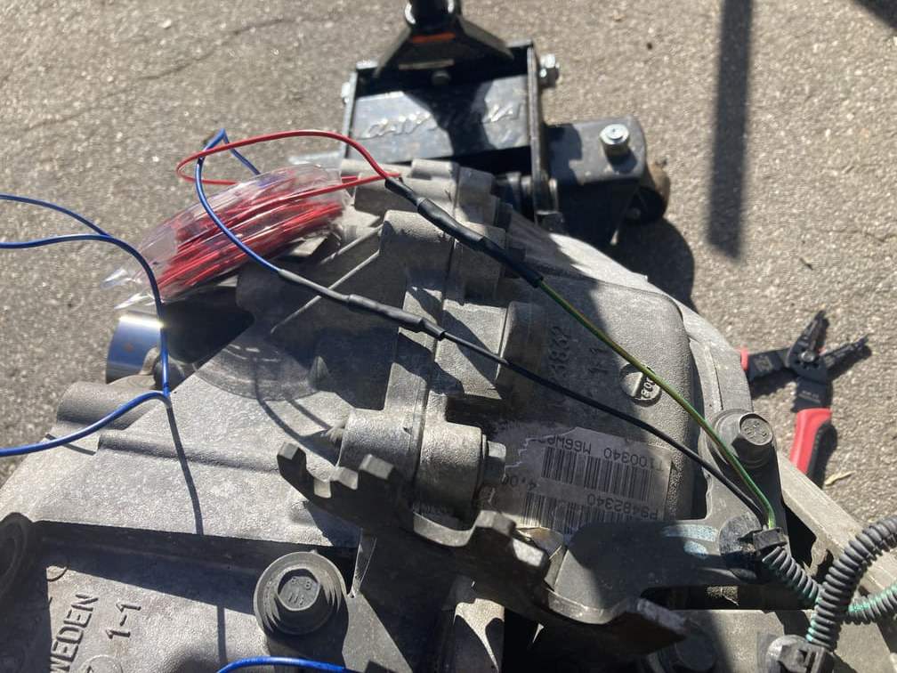
The Tranny: After a deep pressure wash and scrubbing, we are ready to re-seal. Here we wanted to replace everything possible on the transmission housing. Since it was out, it was very easy to swap these parts. This included the reverse sensor, the axel seals, the collar sleeve and all seals, the fill and drain plug and washers, as well as the powerflex poly tranny mount bushing. You can see that external rebuild here:
Final Check List Before Go
Okay, at this point we have everything and our auto tranny is clacking after a hard canyon run in geartronic. We’ve pulled out all the parts and done an inventory and we are ready to go. We are hoping we don’t have to take any drives down to the dealer, but it may happen if we run into some last minute issues or somehow forgot something along the way.
Creating a Timeline for The Swap
So here we are. I’ve been not only putting myself to sleep mapping out the attack, but been having dreams about shifting the 6. Our plan is to get to a “weekend clutch job”. This meaning if we can get the hardware installed prior to a Friday, then we will simply be doing a clutch job, which should take some prep Friday night, and be on the road by Sunday. The variable here, is that we need a “flash” from Hilton Tuning that will take a few hours, and must be scheduled in advance.
So for this reason, we are going to knock out a few things we can, that will leave the car drivable, until we confirm our flash appointment and also friends and tools to help out. This will include the interior tear down, clutch pedal install, the brake/gas pedal swap as well as some engine bay tear down. At all of these stages, the car will still fire up and drive, and then we will just await time constraints to move into the full process. But since we can still drive the car, lets do it!!! Go for Kenda!
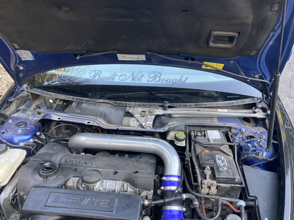
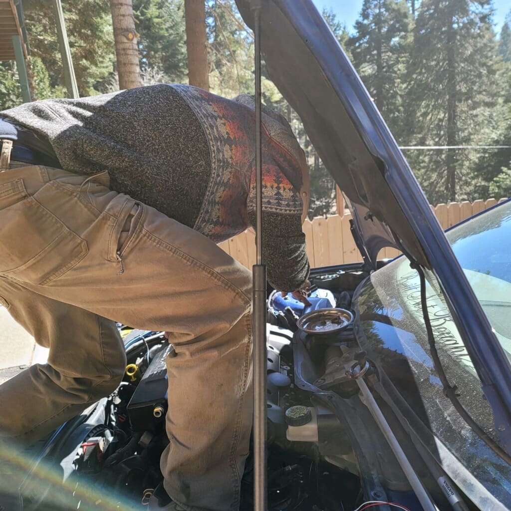
Swap Day 1 – Wednesday: Interior Tear Down, Clutch Pedal Installation, Engine Bay Prep
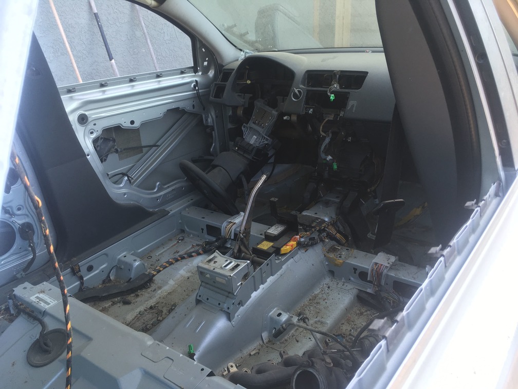
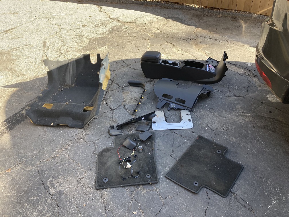
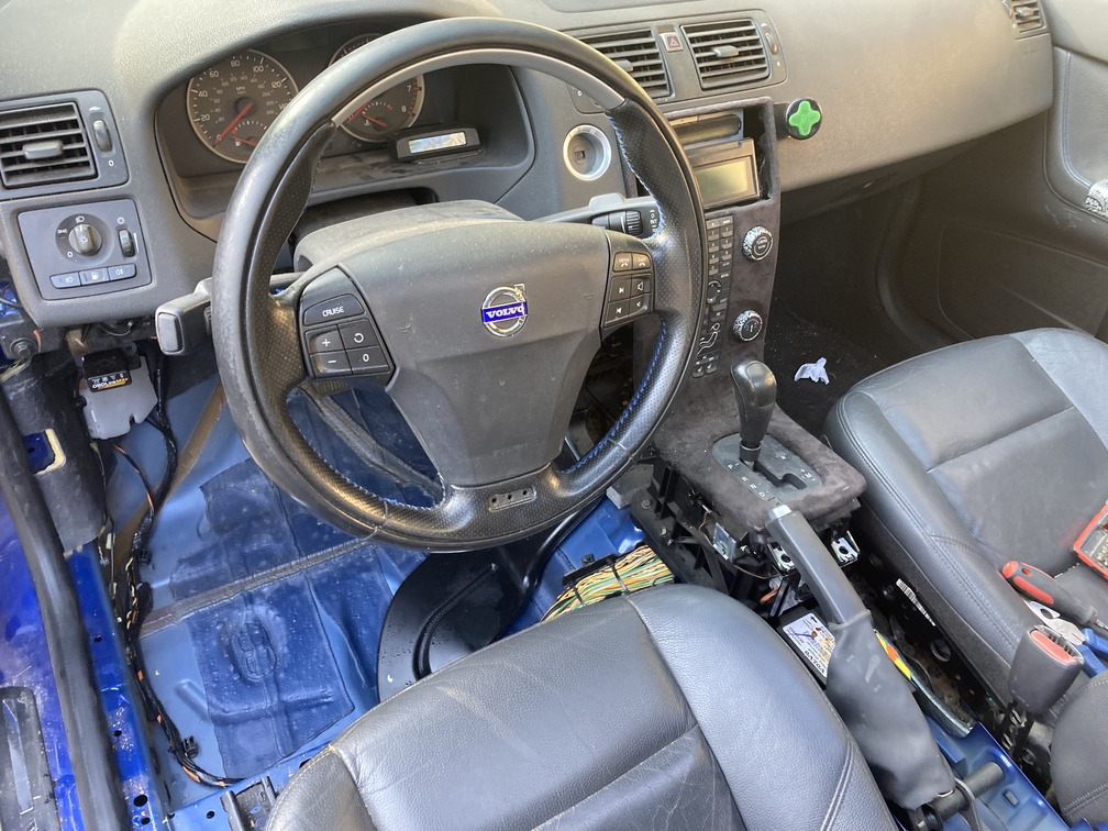
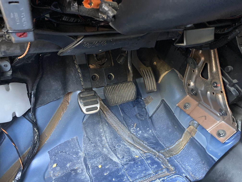
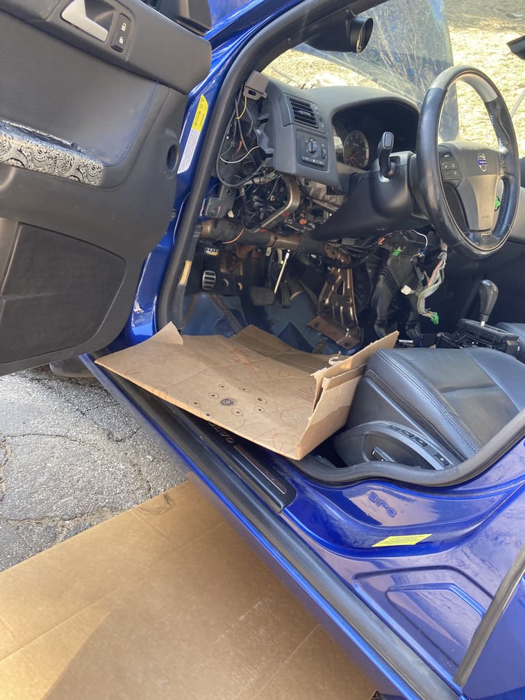
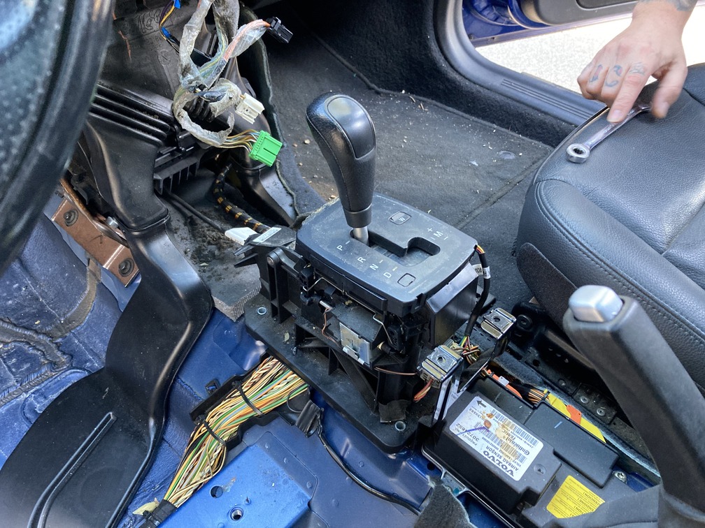
I start by removing the major interior panels that will need to be out of the way for the interior hardware to go in or be swapped. The main parts inside the cabin will be the clutch pedal installation, the swapping of the auto brake/gas pedal assembly for the manual set (brake pedal is not as wide) and finally the shifter assembly.
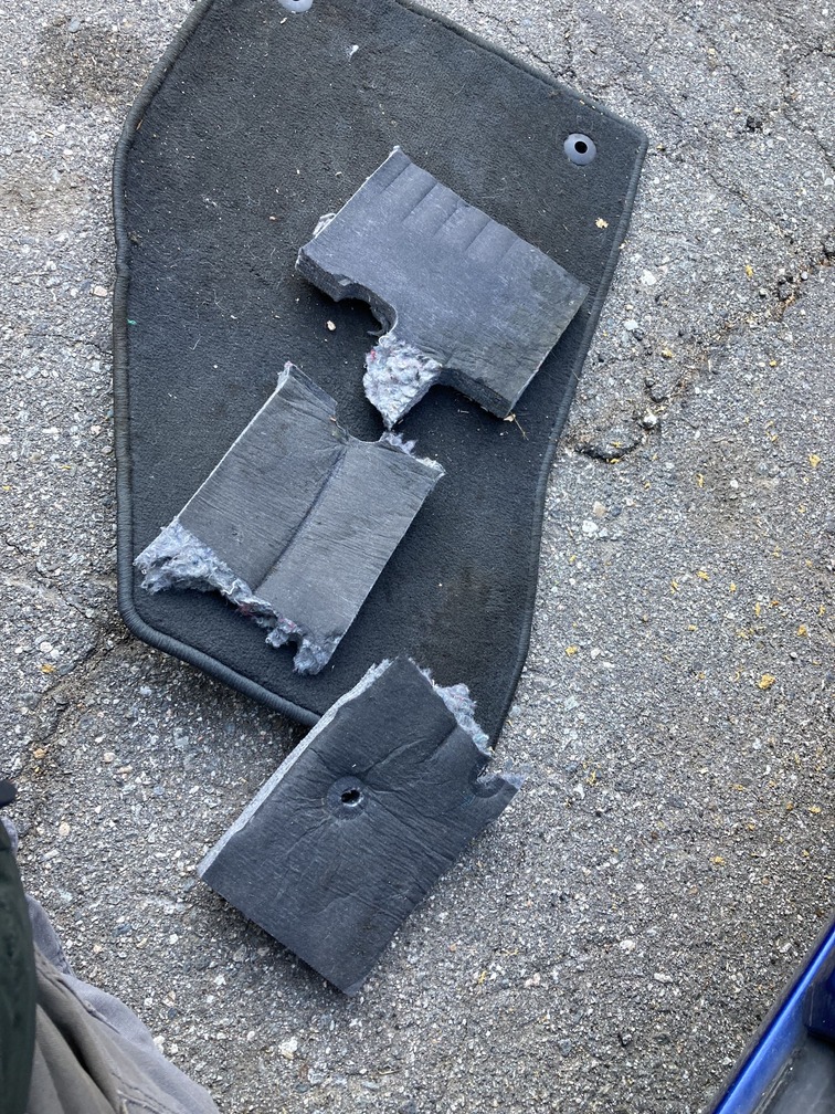
For this I knocked out about an hour of super familiar tear down inside the cockpit. We’ve already done the white to black full interior color conversion, as well as countless radio things, so this was quick and all with a T25 torque bit and a 13mm for the seats. Removed the waterfall, the center console, the driver side lower dash trim, as well as the seat, which gives access to pull the driver side carpet out. Carpet you ask, yes while the pedals can go in with the carpet in place, I remember last year cutting the carpet out at the junkyard and on the donor to get full access to remove the shifter/firewall bolts and have room to feed those shift linkage lines through. So while I am here, they came out.
Now we hit the clutch pedal installation.
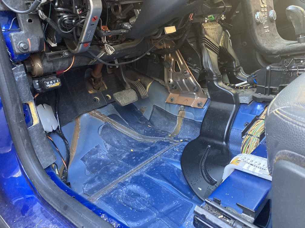
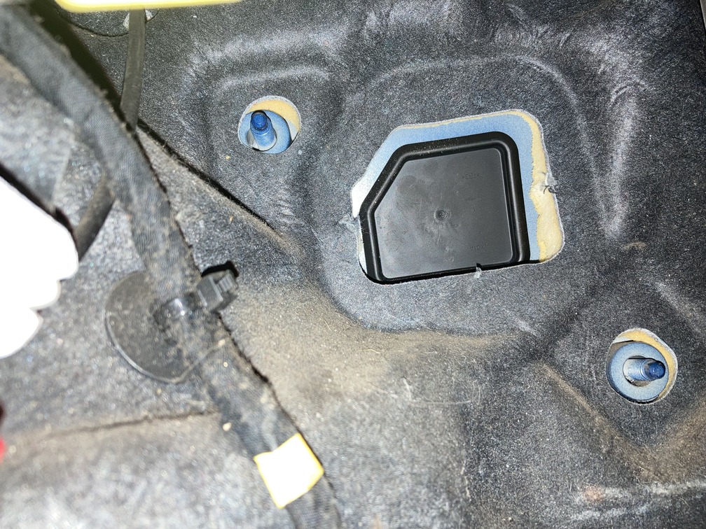
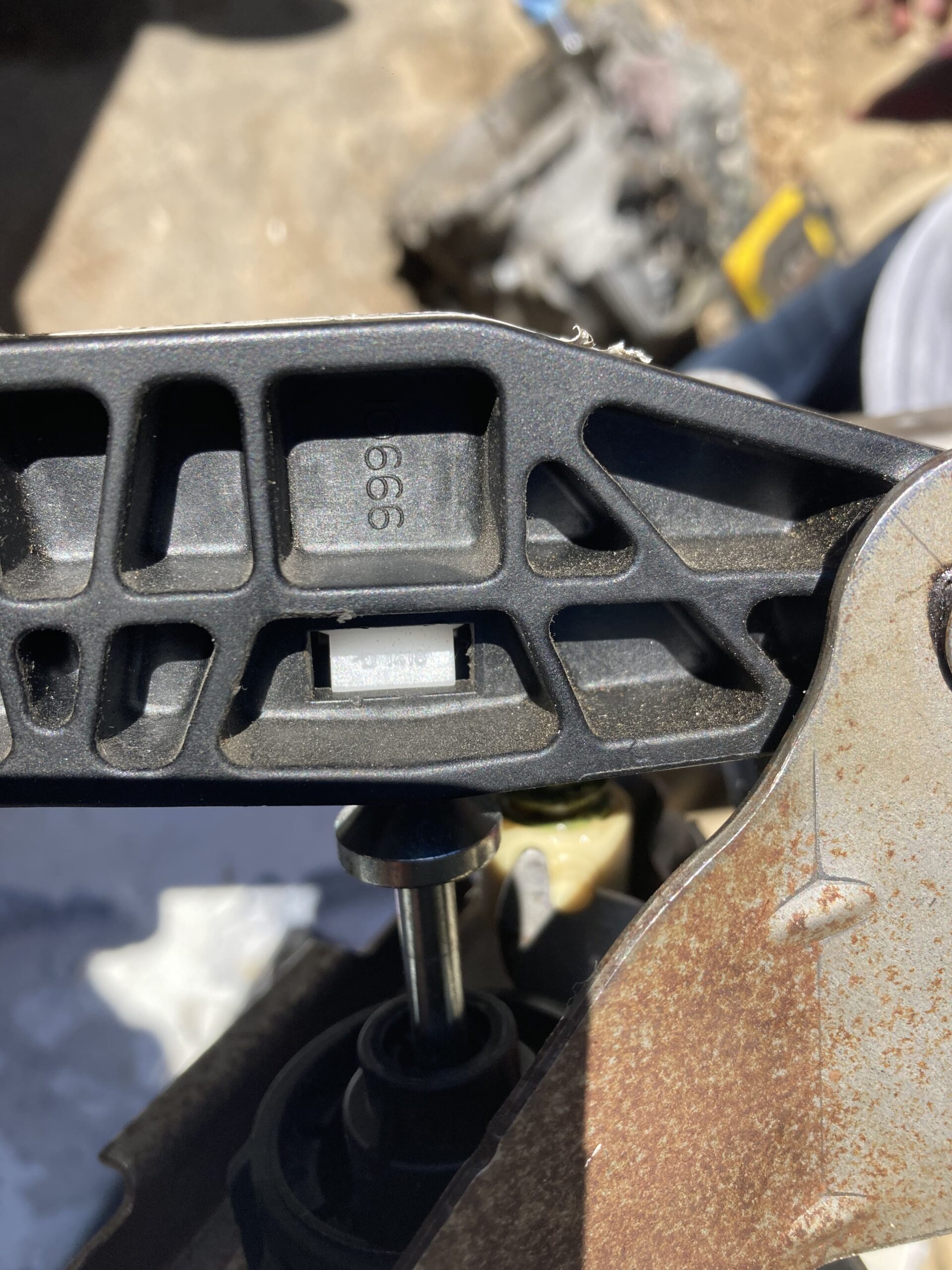
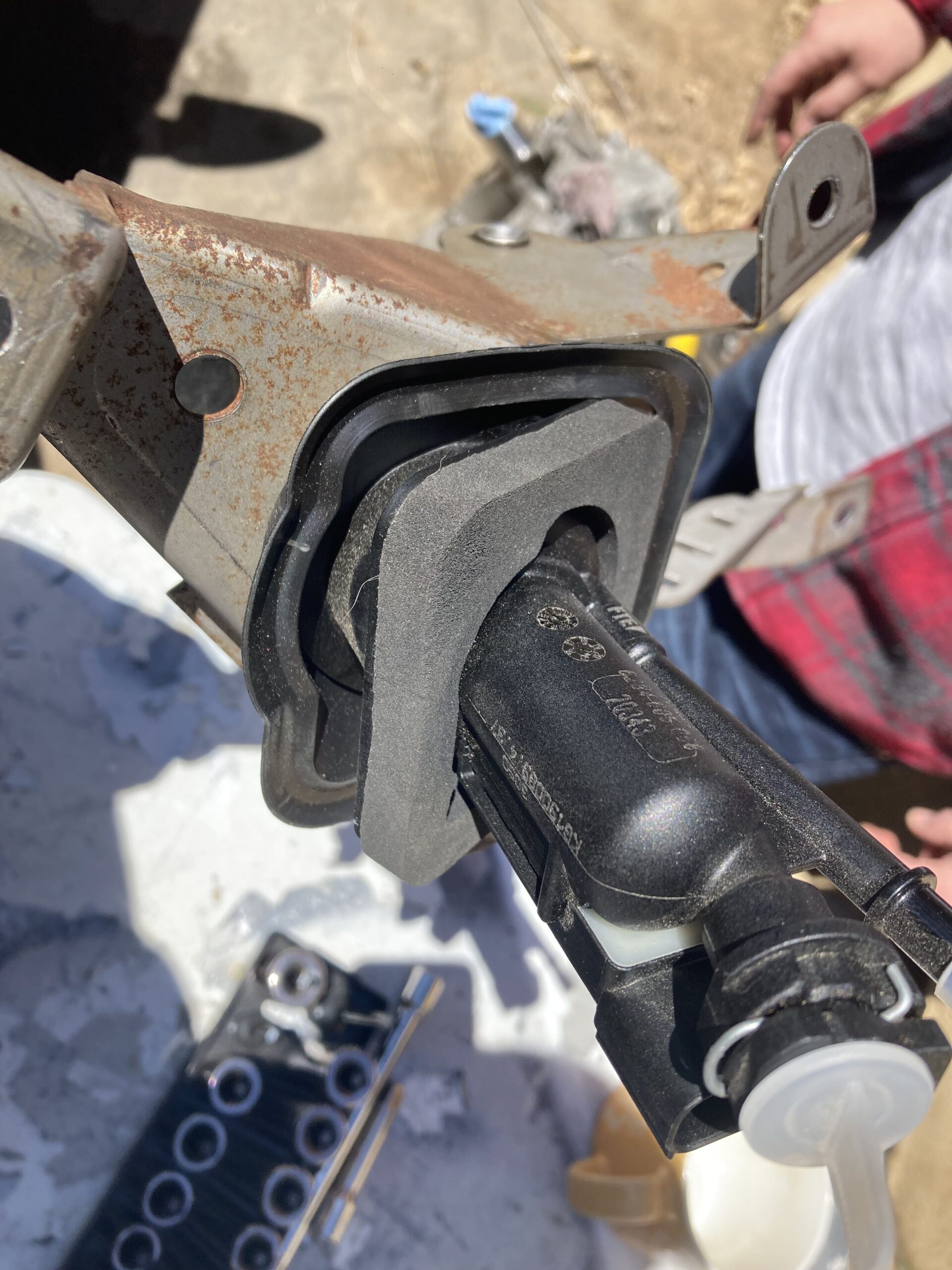
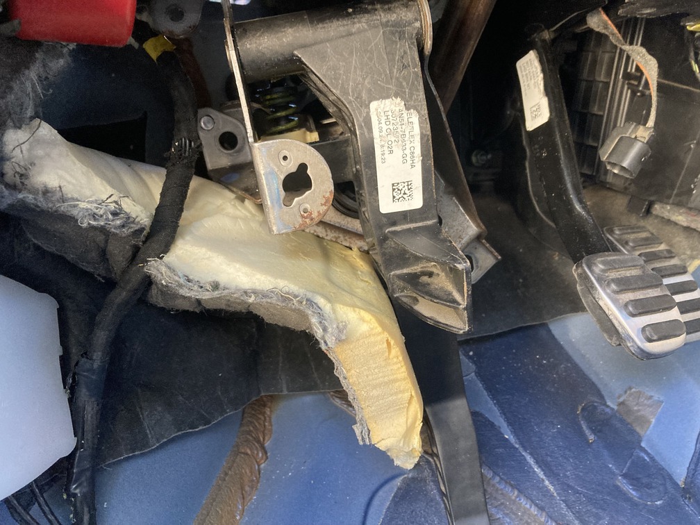
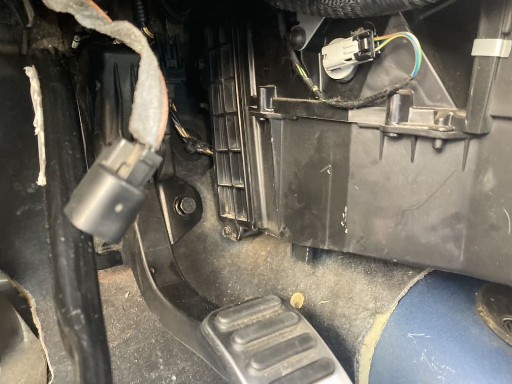
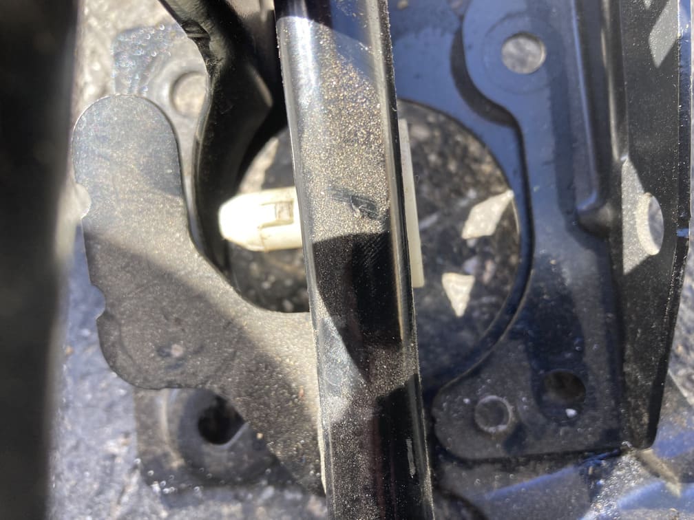
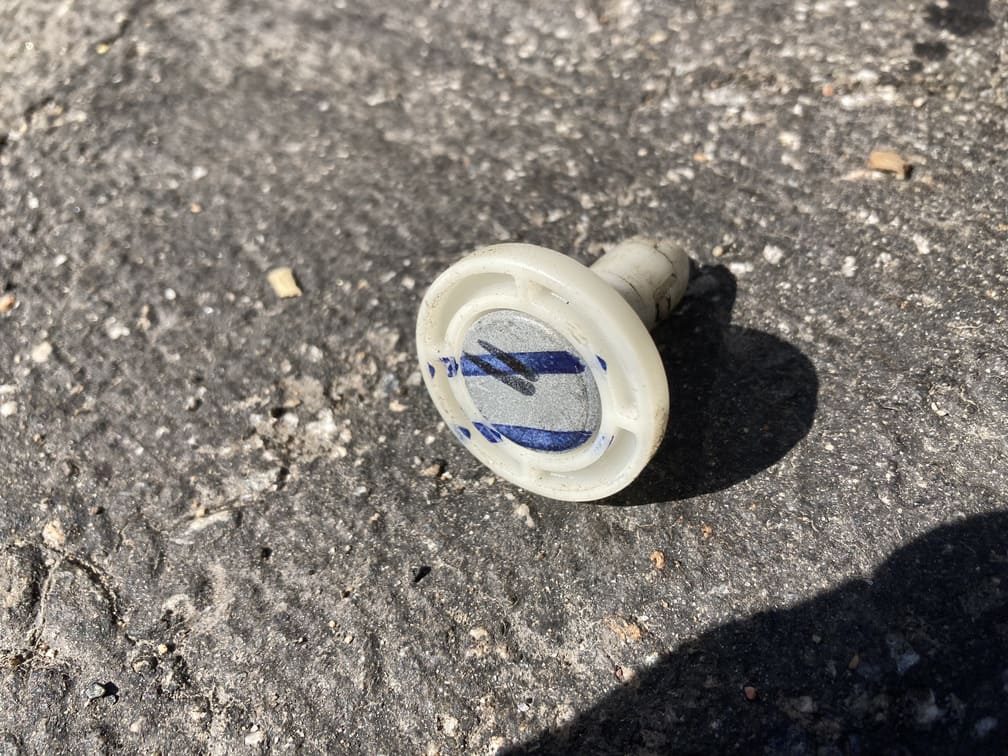
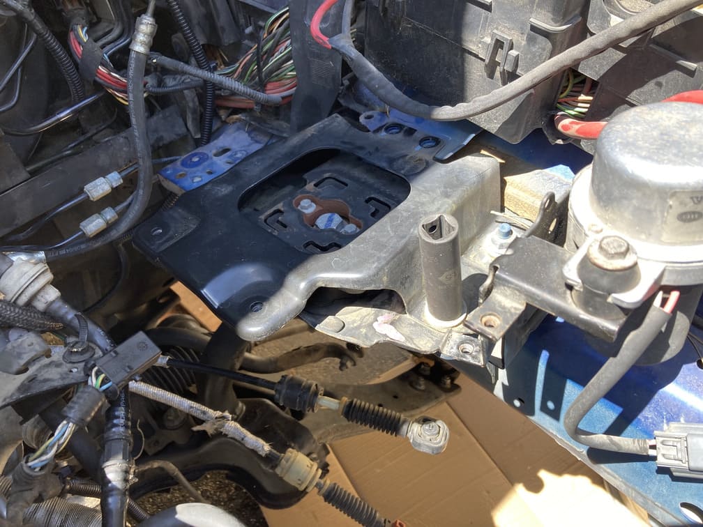
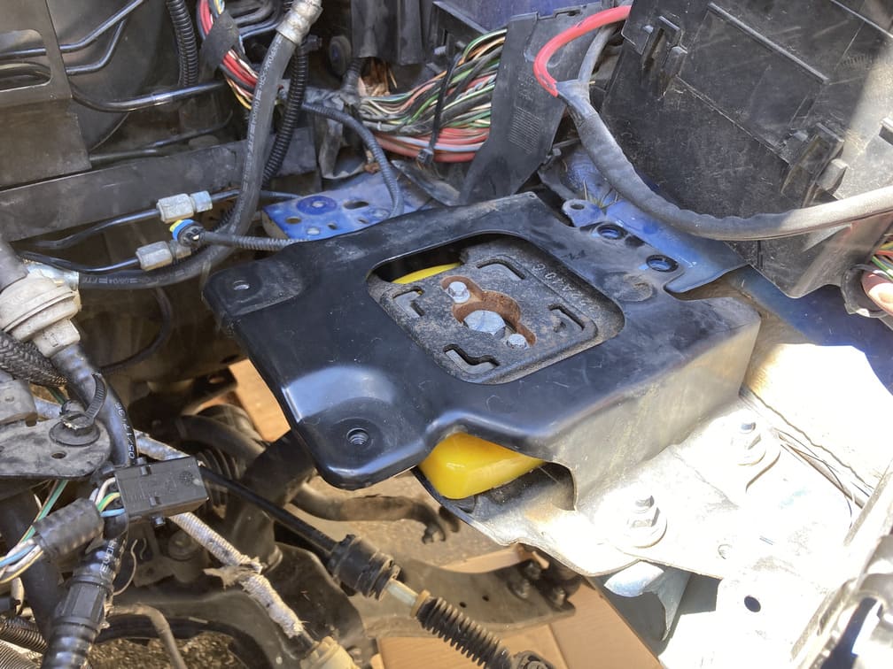
Thank you Volvo for using a universal firewall on the P1. This means there was simply a carpet plug and then a firewall plastic cap to remove and our clutch master will slide right in. Flathead driver and those pop right off, giving your clutch pedal and accessories full access to the engine bay.
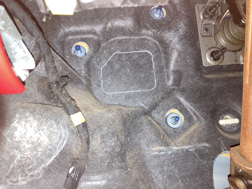
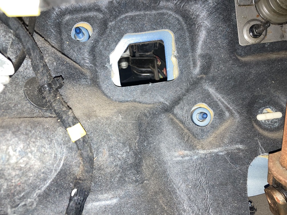
From here we take another look at the clutch pedal bracket to get familiar with the four firewall bolts that need to mate with the pedal bracket and get secured with 4 matching 13mm nuts.
I am now having flashbacks of pulling the pedal off twice, once at the junkyard and once in my garage with the donor car. That top nut is gonna be a bitch, but no one said this swap was easy, come on now, this is actually the first fully documented M66 swap on a P1.
PRO TIP: We installed the pedal assembly without the master cylinder, for some reason thinking it would slide through the firewall. WRONG. We had to go back and remove the pedal assembly, and then work to get the master cylinder and pedal assembly in together, inside the cab, which wasted hours of time.
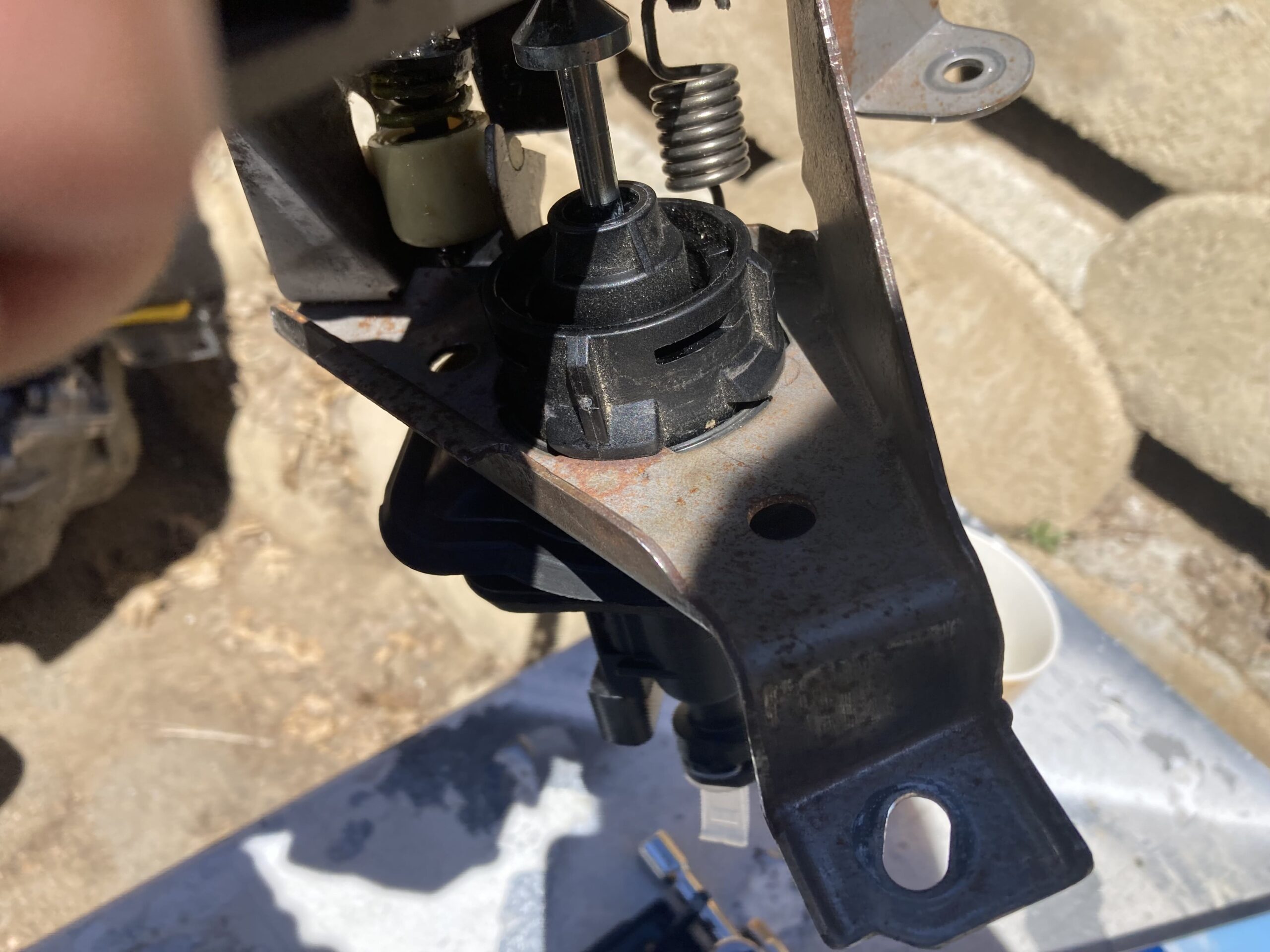
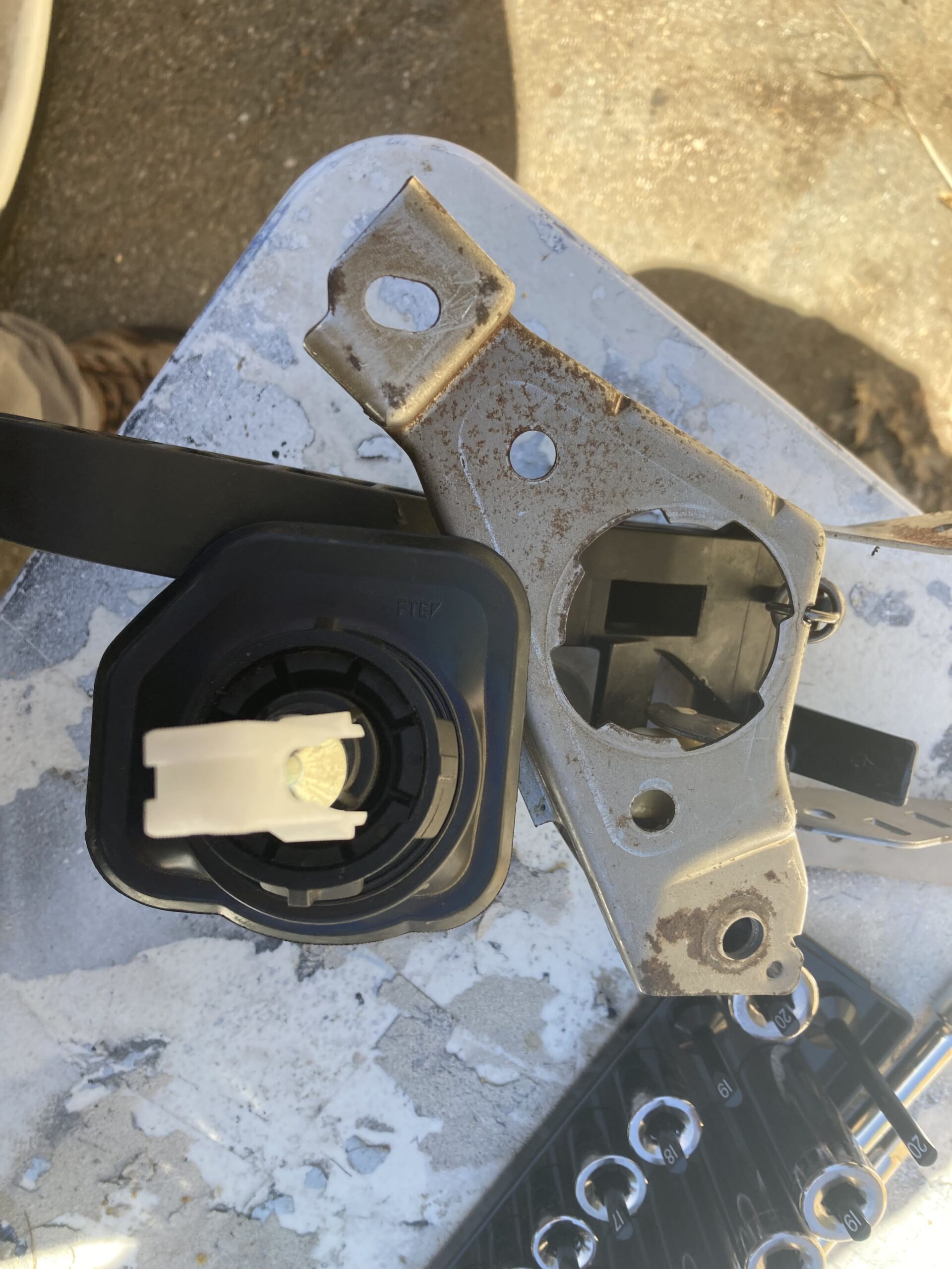
Fast forward to day 3. For reference, get familiar with how the master mounts to the pedal bracket, really familiar, once you are inside the car, upside down, under the dash it is easy to get confused.
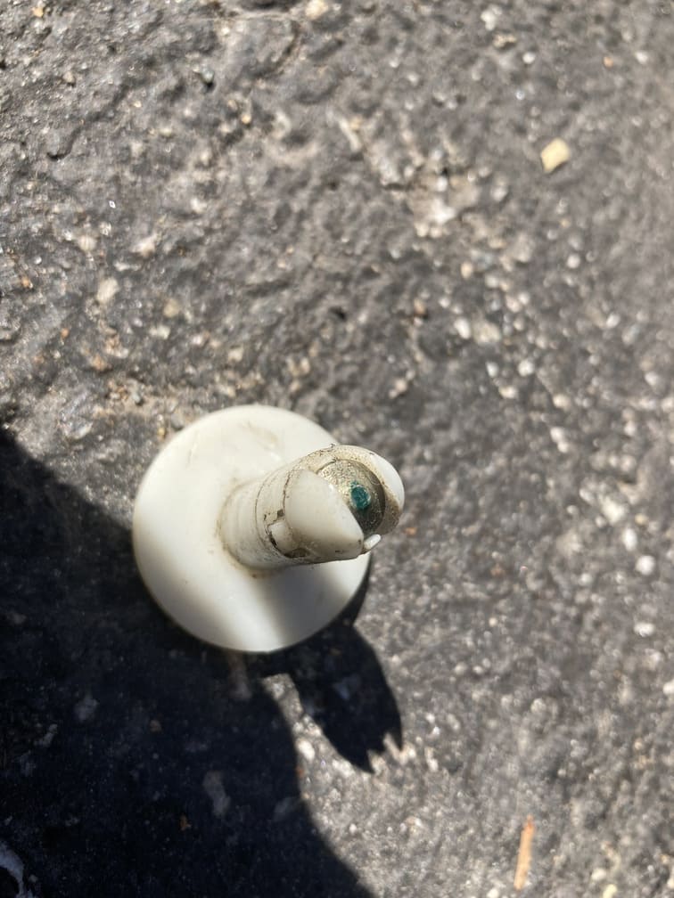
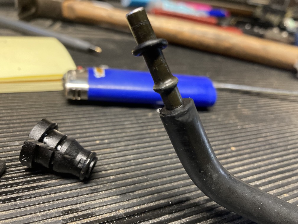
There are four plastic raised tabs on the master, that go into 4 notches on the pedal, one is larger, meaning it can only go in one way. Once seated, a 45 degree turn counter clockwise locks it in. It is tight, so we put some Lucas oil stabilizer on the meet points to allow a smoother turn to lock.
The trick is to remember the rounded edge of the master’s rubber seal will start at 7o’clock, and when seated and locker will point down to 6o’clock.
Also be aware of the white plastic locking clip on the arm that will lock into the pedal shaft.
The next part, can’t really explain other than the master and the pedal assembly can’t really go in assembled, or can they, can’t remember even though it was two days ago. I tried every which way to get them in together, but space is the issue, and you don’t want pressure on the master lines since they are plastic. This then presents the problem of having to assemble to two pieces under the dash. What we did was cut a slip in the firewall carpet from the hole in the firewall down, and then folding it towards the driver door. This gave us an extra 2″ or clearance for moving stuff around.
Make sure the pedal is in the closed position, providing the slimmest profile for getting it in. Eventually you have both pieces in behind the dash, and you need to assemble them. We partially put the master into the firewall, and then positioned it with the rounded rubber at 7o’clock, then tries to seat it in the pedal, after struggling for a while it was lined up with tabs and notches, so we pulled it into the pedal and tried the last 45 degree counter clockwise turn to lock it in. The oil helped, but we ended with some large channel locks, and be careful here as the whole thing is plastic…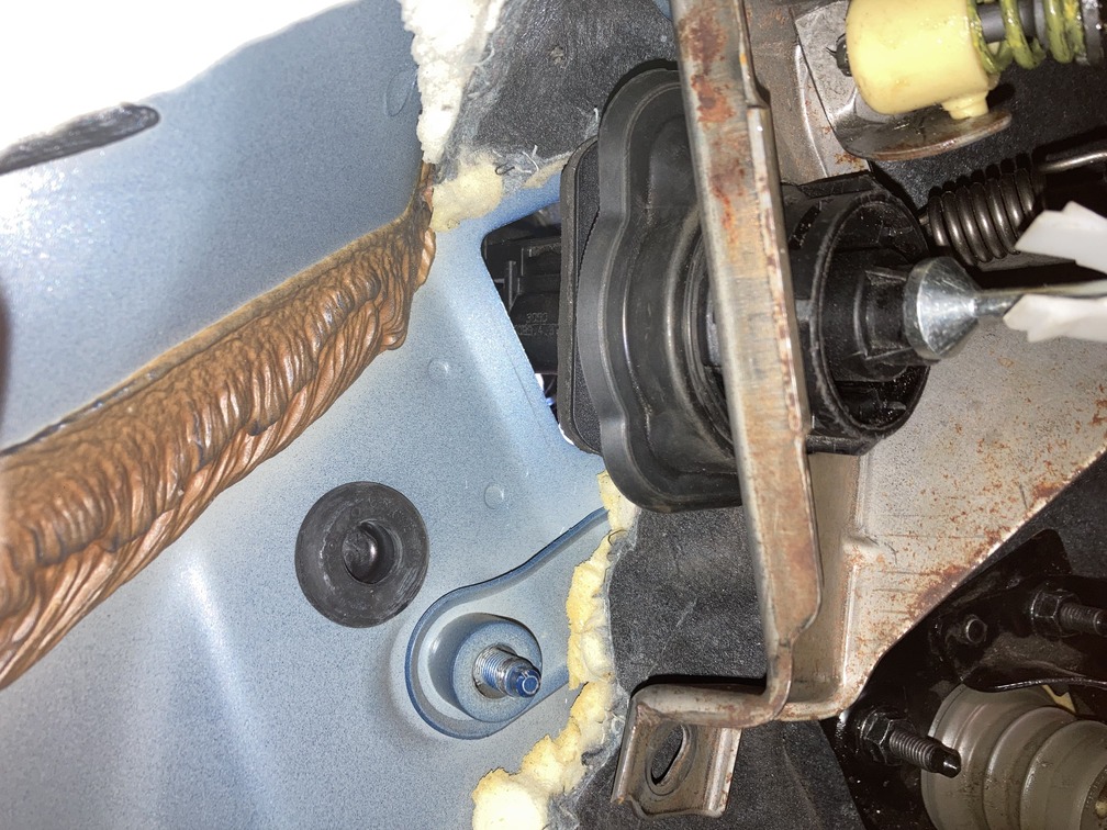
After it is in, push the white clip tab into the pedal locking the whole unit together. Then, you move on to mounting the bracket….. for us, again….
I seat the pedal bracket onto those firewall bolts and thread each of the lower a few threads to hold it in place. The bottom two are no issue. The lower right you can go straight in, same thing with the upper right. I ratchet them down a bit, but leave some give to make sure the left side has play to get them seated. Again though, this is because the lower dash plastic AND the metal kick guard were removed.
Pro Tip: These bolts were painted over by the factory, so they will be a bit rough and take some gusto to get the but on with the extra layer of thick paint covering them.
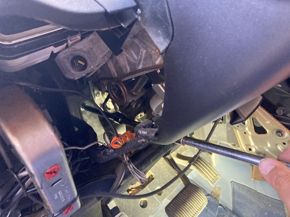
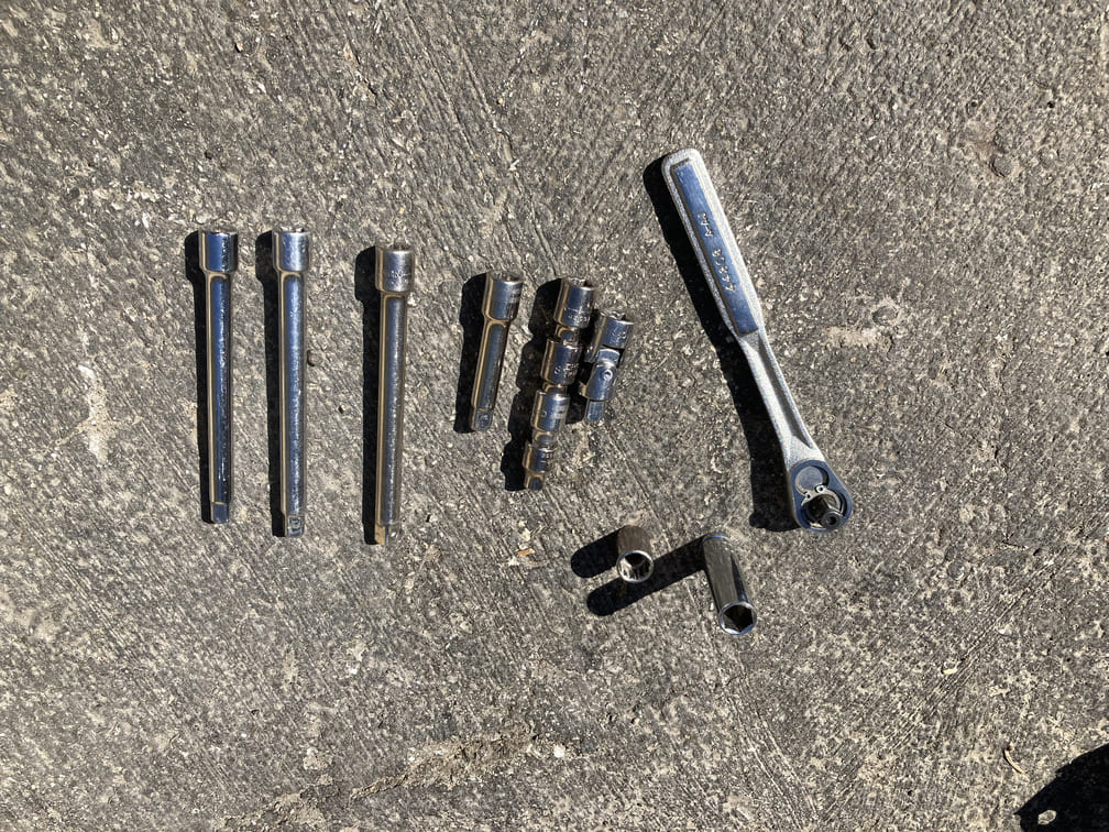
Next the lower left nut needs to go on. Here I placed a nut inside of a deep socket 13 and fished my hand into the area and tried to grab a thread or two. After that, I switched to a standard short 13mm socket immediately mated to a swivel extension and then 2 more 6″ extensions.
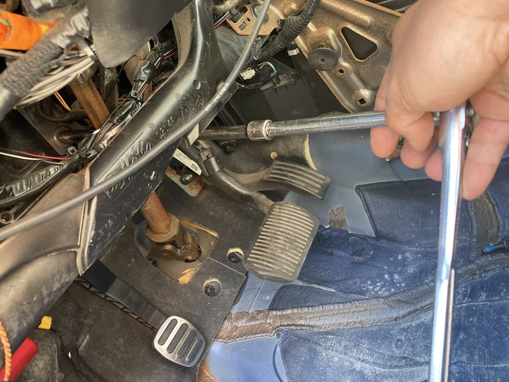
Now for the fun part. With a 13mm ratcheting wrench (socket wont fit as it has no room behind the gauge pod), on my back, upside down, with on foot on the door and the other on the center pillar, I squeeze my right hand way up behind the gauge cluster, and at the end of the process found that putting your left hand over the crash-bar, under the dash, gives good access for a two hand wrench effort. A quarter turn at a time….. for an hour.
Here you can see right hand with wrench, and way up there is the fourth nut.
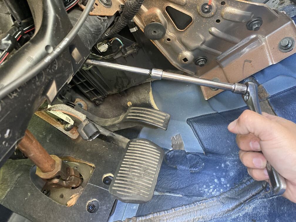
And this trick, I wish I found earlier, the left hand above the crash-bar, under the dash, made quicker wrenching, was able to do almost a half turn this way.
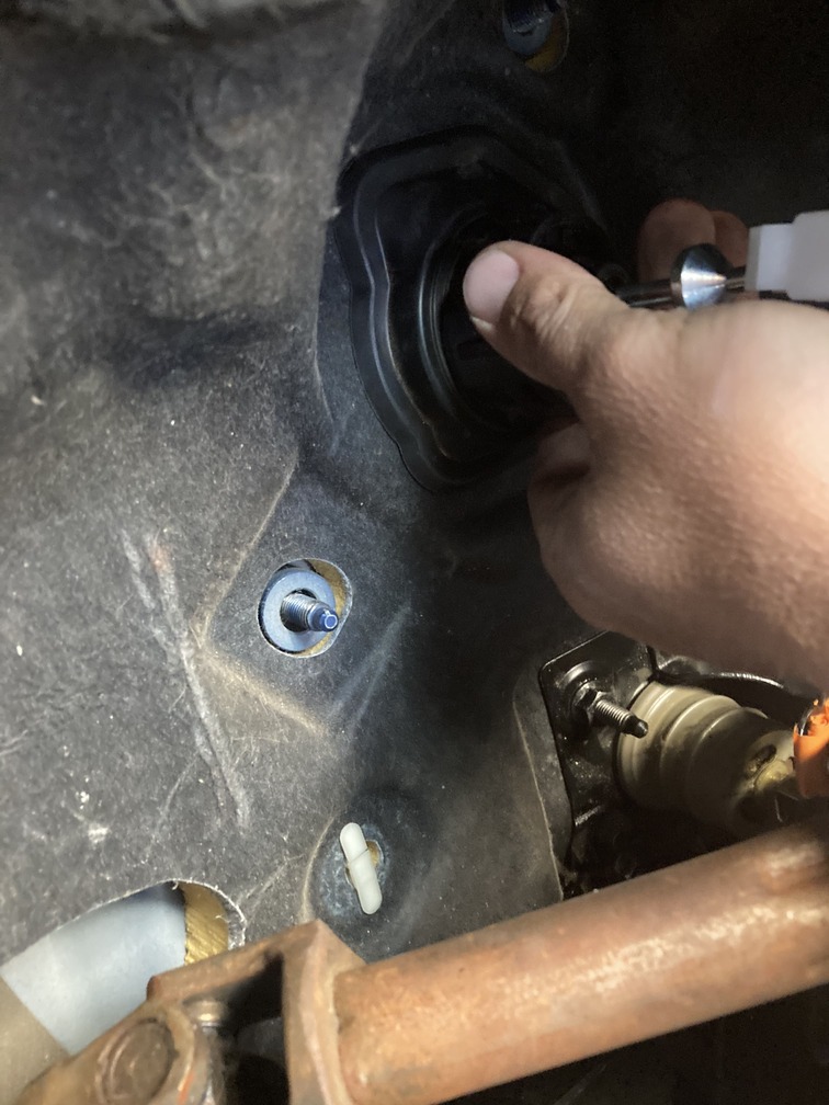
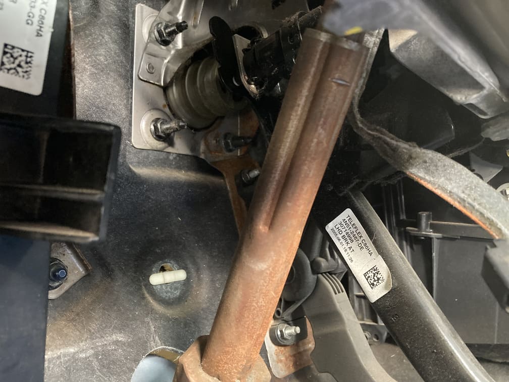
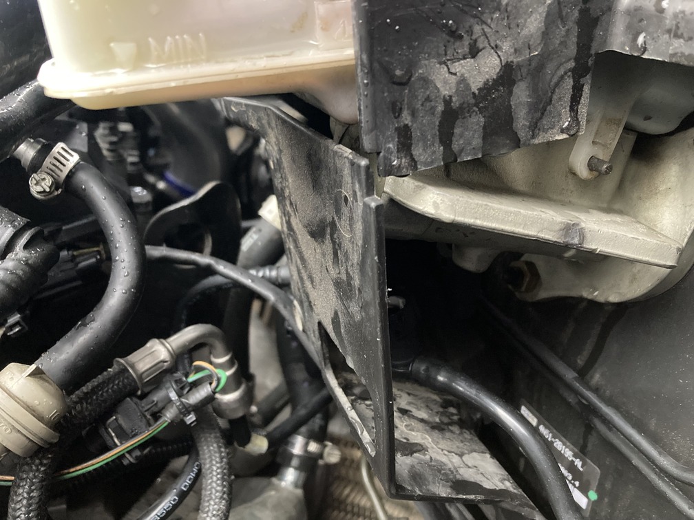
Flashforward a few days, and you can see the master through the firewall, ready for hookup.
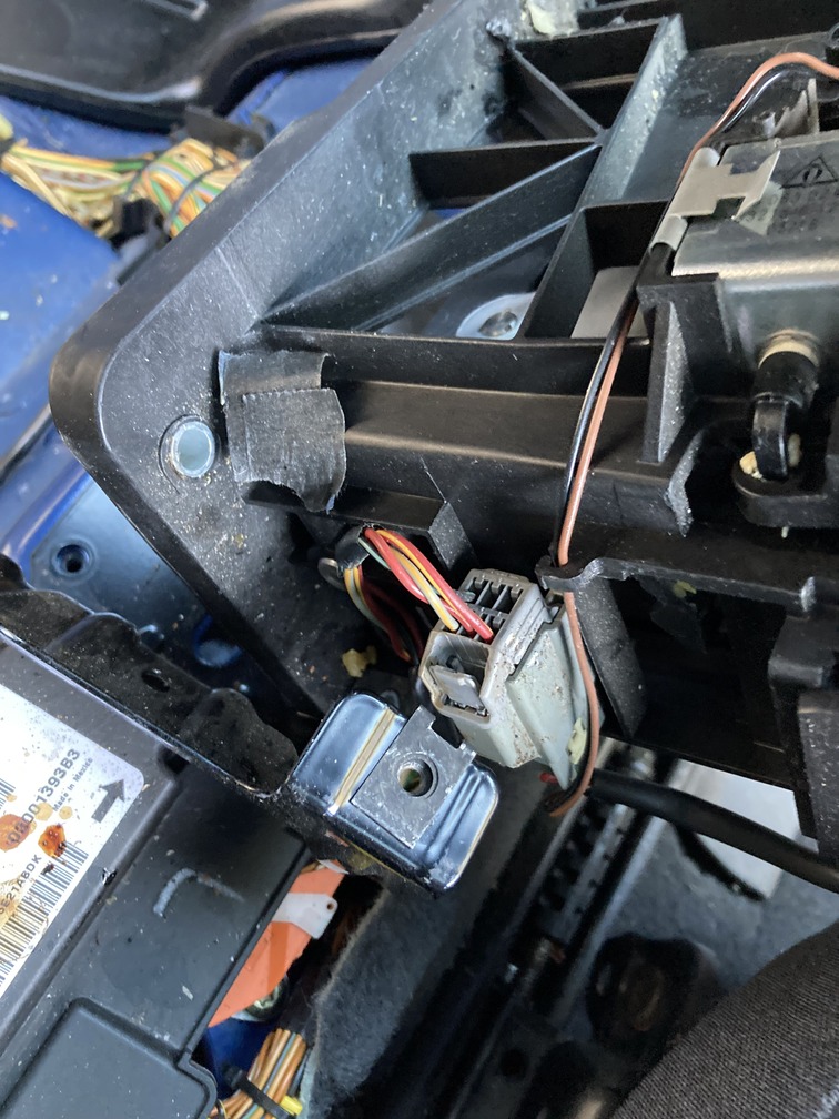
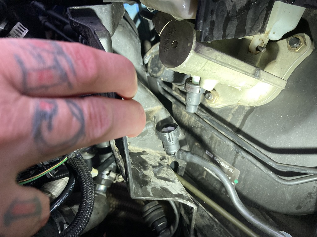
This is one of the lucky moments in the swap. The wire harness already has the connector for the master on it, unused and capped. Cut the tape holding it to the loom, remove the cap, and you can plug it into the master.
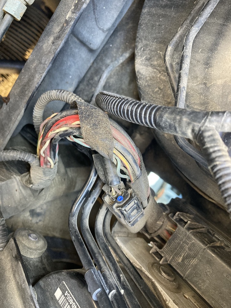
From there, you can connect the clutch pipe (hydraulic line to tranny) and your master to brake booster line to the master. Do not connect to the brake master as it will feed fluid into the clutch master, and we are not there yet.
Flash back to day 1…. Can’t wait for the other 2 pedals. But for now, I remember that the top brake/gas pedal bracket was 10X harder. So will will save that for it’s own day, and allow for breaks and time to throw tools and cuss out anyone who dares to ask if I need a hand.
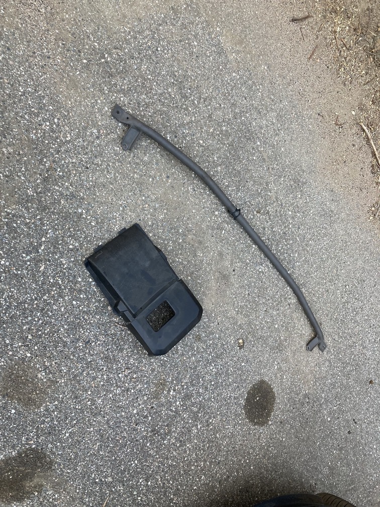
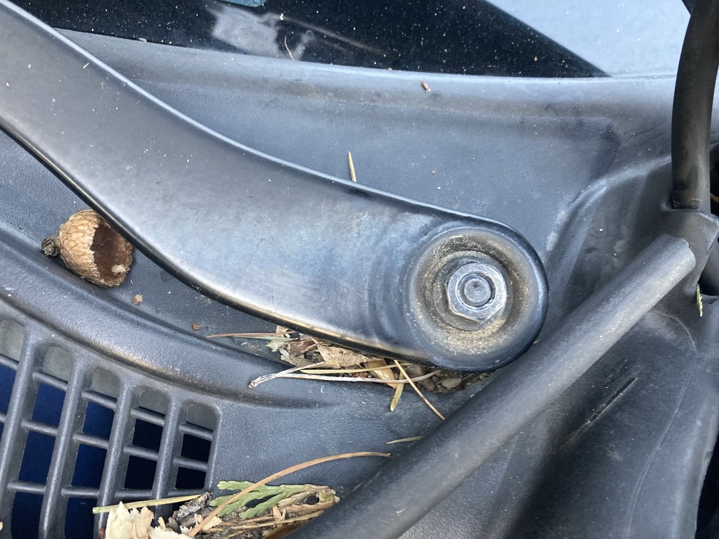
From here, we still had a little sunlight, so we moved under the hood to pull off some quick parts. This included the strut tower trim panels, the strut bar, the wiper blades and the wiper cowl.
Strut tower trim covers pop off. 13mm for the strut bar, if you have one. Flathead the nut cover on the wiper blades, then take that same 13mm and pull those nuts off. From there pull the outside rubber trim from the wiper cowl away from the fender towards the center engine bay. That will pop out, and toss it aside. I replaced the nuts and covers so we have less hardware piling up.
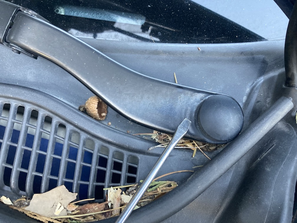
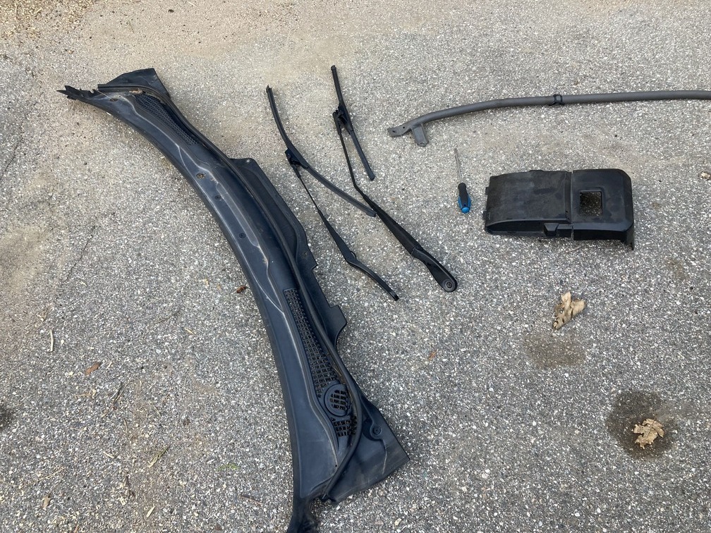
Pro Tip: 5 seconds after pulling the wiper blades, I notice they were different and did not note which was which. Luckily my windshield was dirty, so I can confirm the driver side blade is the longer one (by about 9 inches).
That’s it for day! See you tomorrow.
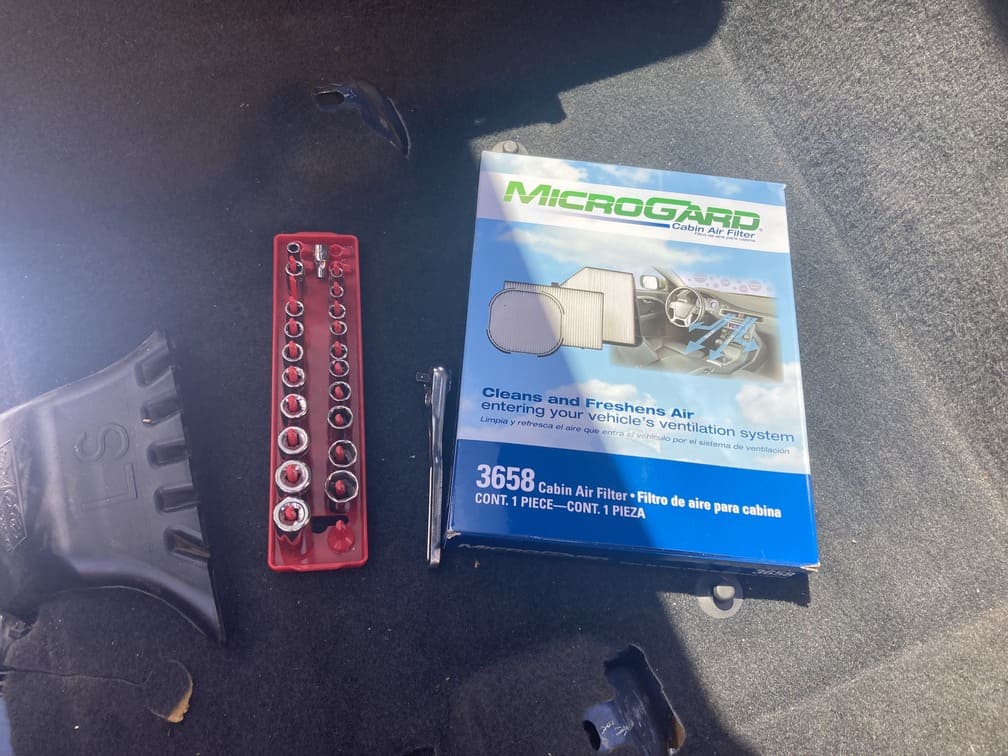
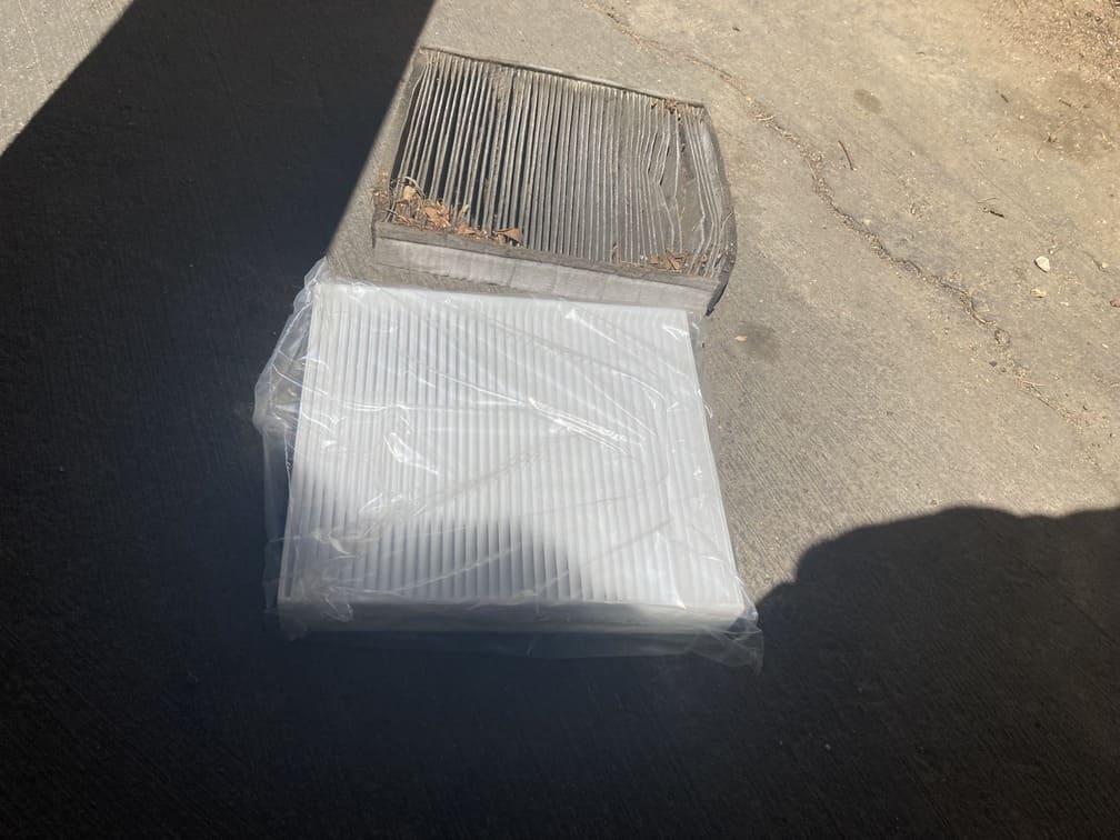
Swap Day 2: Saturday (took 2 days off) – Brake/Gas Pedal Removal and Installation…and a bonus cabin air filter.
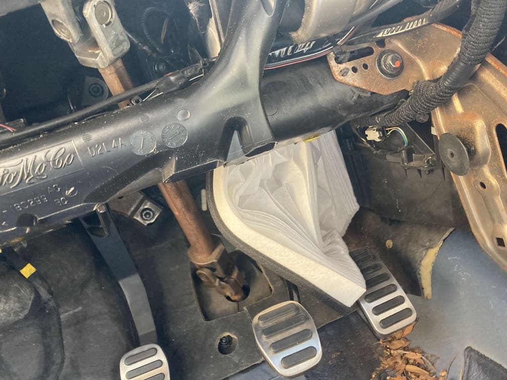
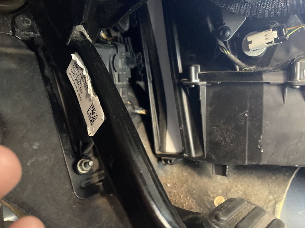
Pro Tip: The cabin air filter on these cars is difficult to change as it is under the blower box, behind the center console and right of the gas pedal, behind a door and under carpet. After your gas pedal assembly is out, swap a new filter in, you will thank yourself later.
We didn’t have this foresight, but still put a new one in after the pedals went in, which was a fail considering a day before they were out of the way.
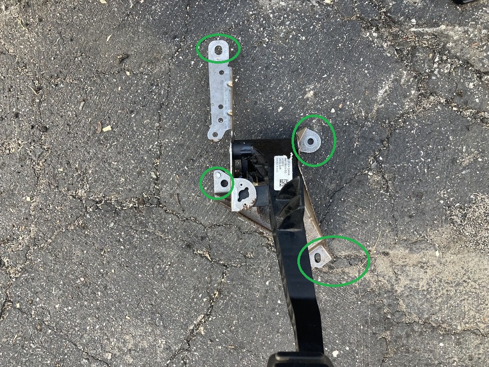
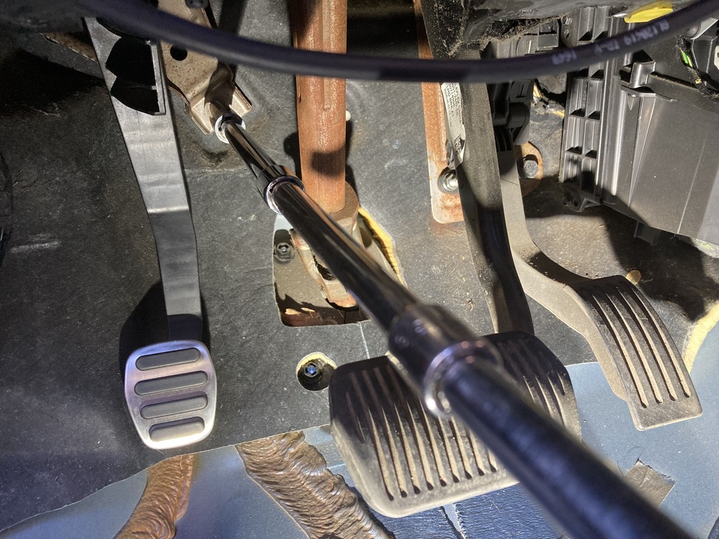
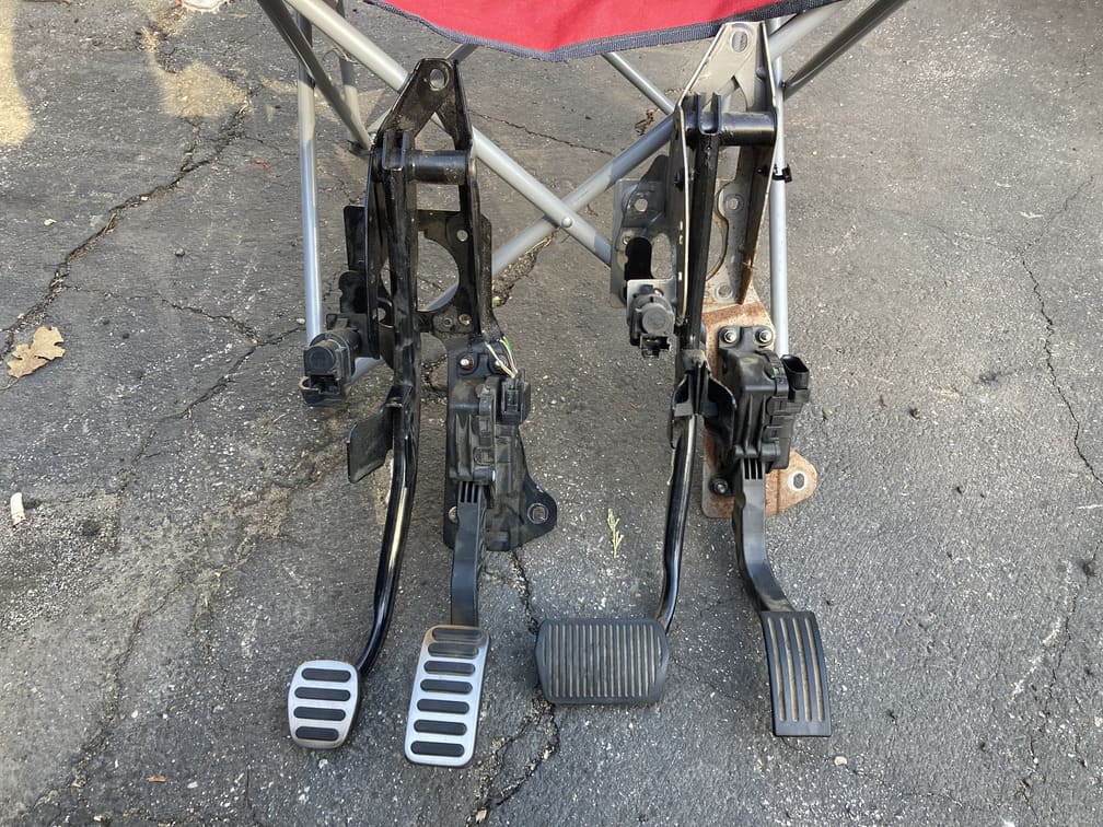
Now here we gear up for some more car yoga, as the brake/gas pedal combo also have a top nut that is way up under the dash behind the gauge pod. Here we see the new bracket for reference on the placement of the 5 nuts and 1 bolt, all 13mm.
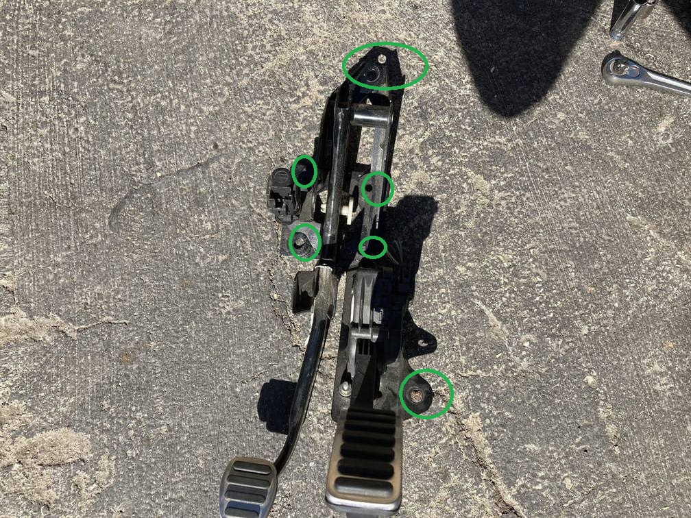
For removal, we grab a deep and regular 13mm socket, as well we every extension and swivel extension we have in the box. Each nut will require a separate length and it’s like a puzzle finding the correct combo for each.
When looking under the dash, you can pretty easily see the lower 4 nuts and bolt to come off. It should be noted the 4 nuts in the middle in a square pattern actually hold the brake booster to the firewall, and the top and bottom are the main mounting points of the bracket to the firewall, but all 6 equally important.
Before we attack the nuts and bolts, lets pull the white plastic retainer pin the attaches the brake booster to the brake pedal. Flat head screwdriver will work.
Now we can work on the nuts and bolt. The bottom right is the only bolt, and you will see it just right of the gas pedal. A double extension gives you direct access to remove this.
Next the first two lower nuts on the bracket, same here, all your extensions piled on, and you can access these directly under the dash no problem.
After that, you need to get to the top left nut, this you can get to from over the crash-bar, going directly in with extensions.
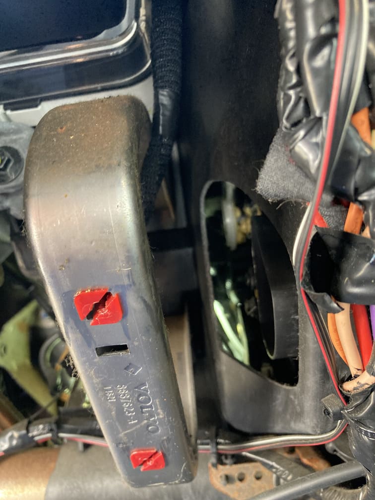
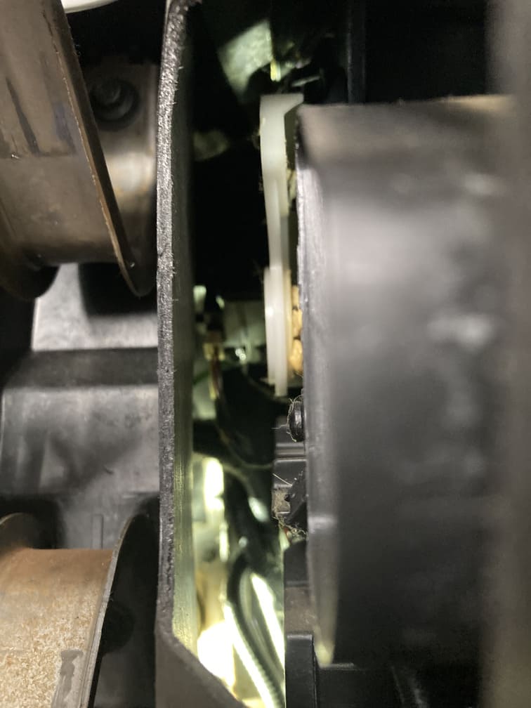
Next is the top right nut. For this we found that removing the floor climate control tube/duct, gave almost straight on access. A T25 and it pops off out of the way.
Doesn’t look like much access, but through here you can get your socket with extensions.
After a while I got smart and tried to save my back from the rough raw ground. Some cardboard added some cushion and made this process a little more bearable.
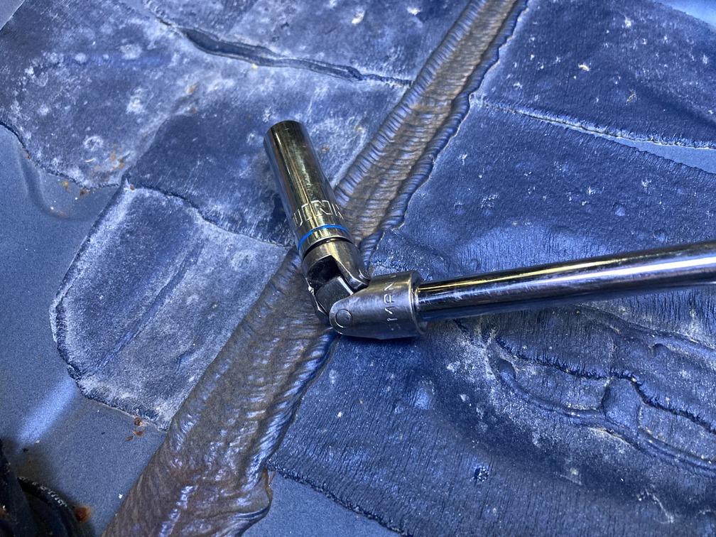
Lastly, one of the hardest nuts of the entire swap, the top pedal bracket. On the donors for removal we had pulled the gauge pod and dropped the steering column, but here we tried a different approach that actually worked. We went from the floor directly up, and was able to gain access with out removal of anything else. It was still a 1/4 turn at a time upside down, but here is the combination of extensions used to get you there.
Any shorter on the extension and the racket can’t turn as it is blocked by the dash, any longer and the racket is in your face. Rachet-short-long-long-swivel-13mm. The other nuts ALL NEED DEEP SOCKET, but luckily this one doesn’t, and that’s what allowed us to go in from the bottom.
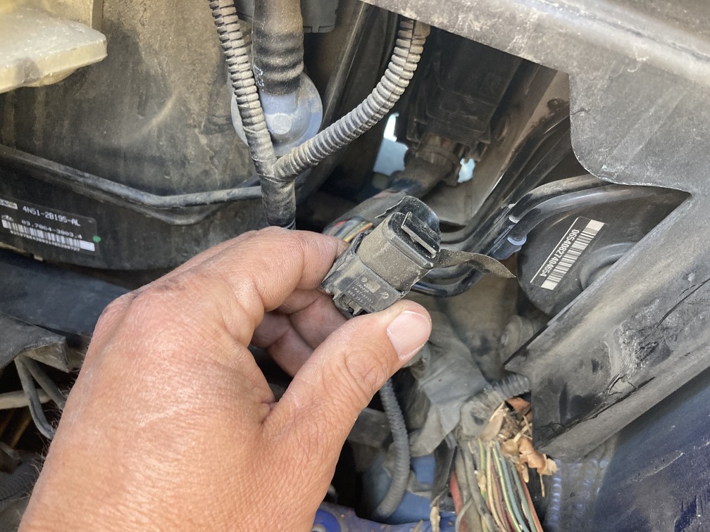
Once that last nut is removed, unplug the brake pedal position sensor, unplug the gas pedal harness, and lastly there are 2 plastic push wire loom retainers that need to pop out to fully free the pedal assembly.
PRO TIP: The swivel extension is at an almost direct 45degree angle. Which means once during a full rotation it will bind and jump off the nut since there isn’t enough room for it to swivel out the binding in the swivel. Just reset and get another turn, and for this, we had replacement nuts, and used a new one in replacement since there was pre-strip on the nut. In case this ever has to come off again, we don’t want any issues.
Maneuver the brake booster fork back, and pull down on the pedal assembly at an angle and work it out, and then victory.
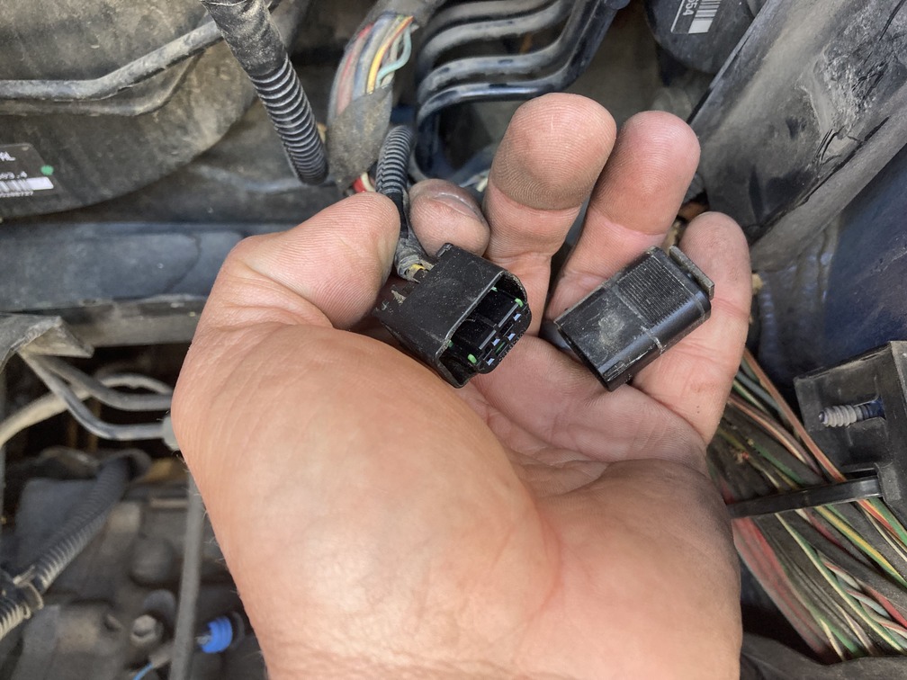
Closer inspection confirms the gas pedals on here are exactly the same, so we will pull our old one off the bracket and throw it in our parts pin in case we need it later.
Replace the new assembly in reverse, hook up and test your brake pedal sensor to make sure brake lights function. Then take it for a test drive. While the brake pedal is smaller, I didn’t notice any difference really.
Swap Day 3: Wednesday (Took some more days off)
Shifter assembly
Planning for the clutch pedal master cylinder, and clutch hydraulic lines, which will require removing battery and battery box. But from above you know we already did the master clutch today, but then we had some time and went at the sifter assembly as well.
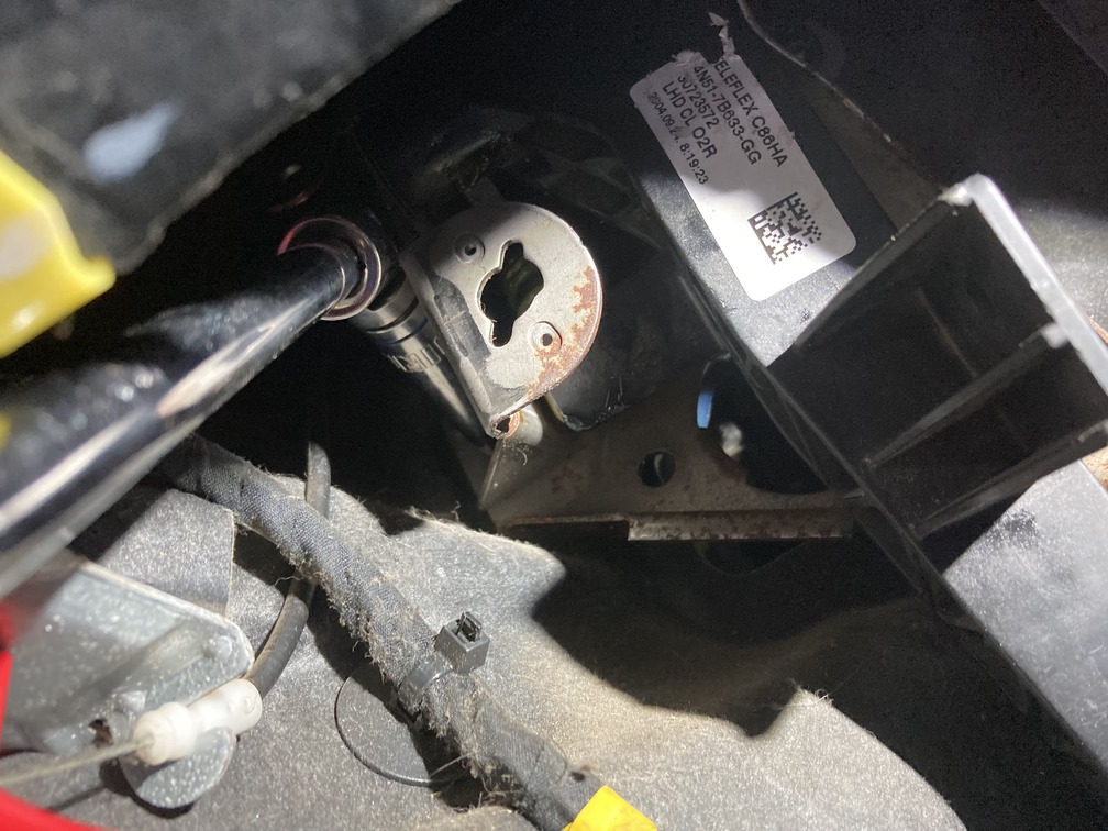
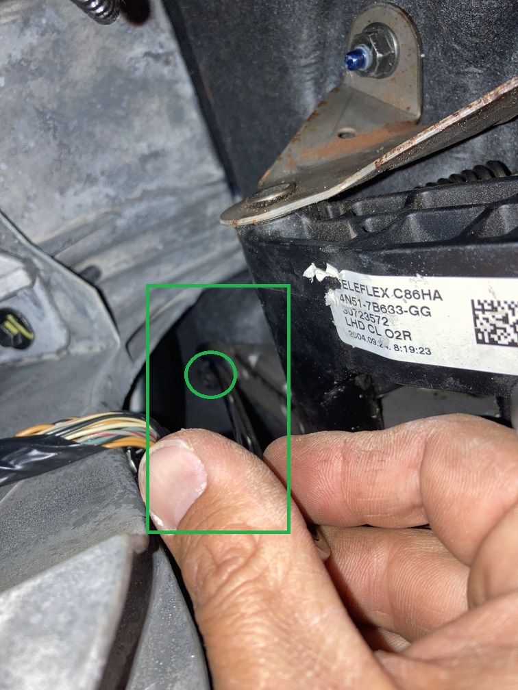
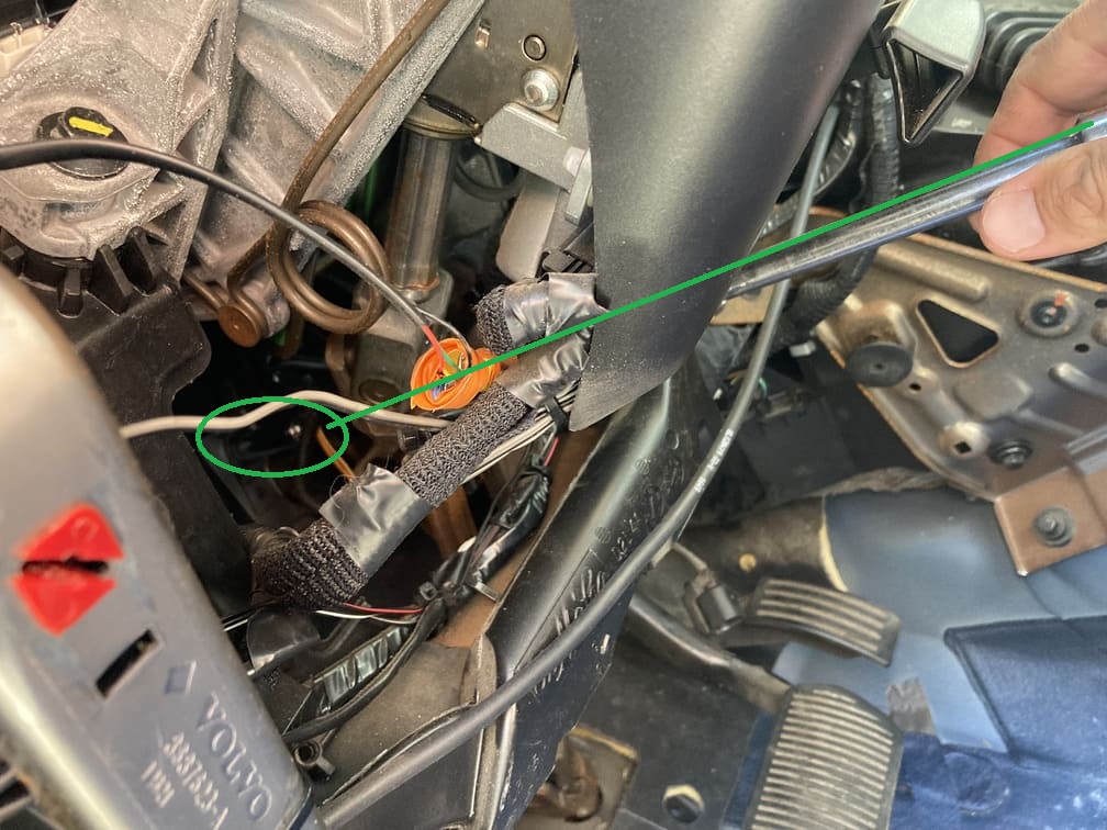
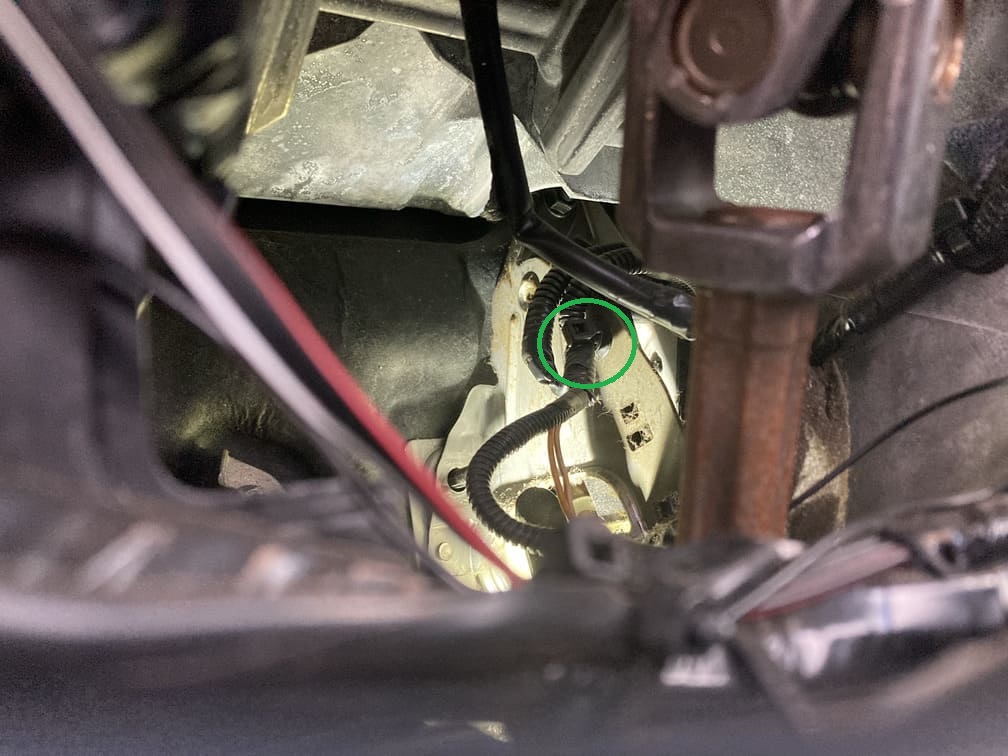
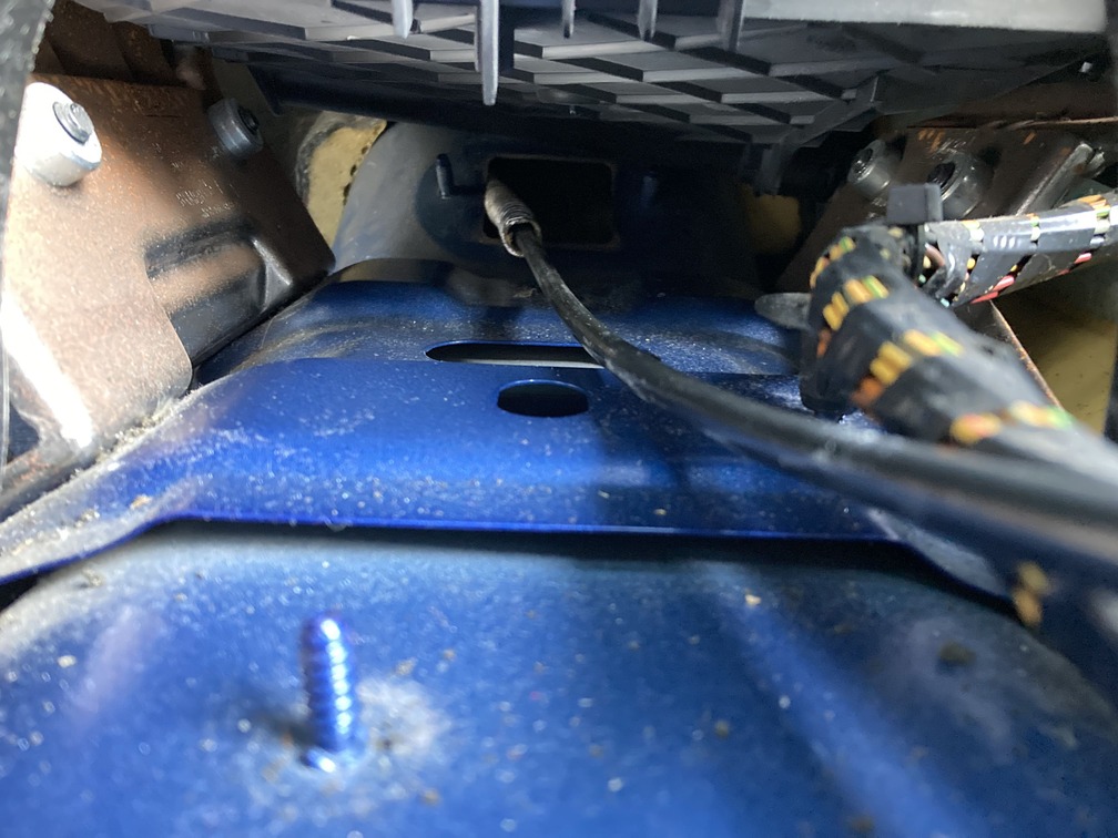
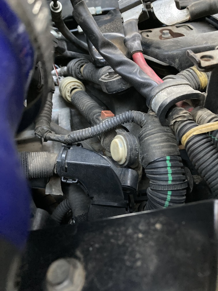
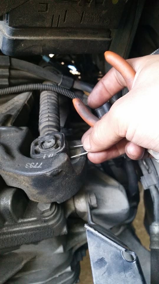
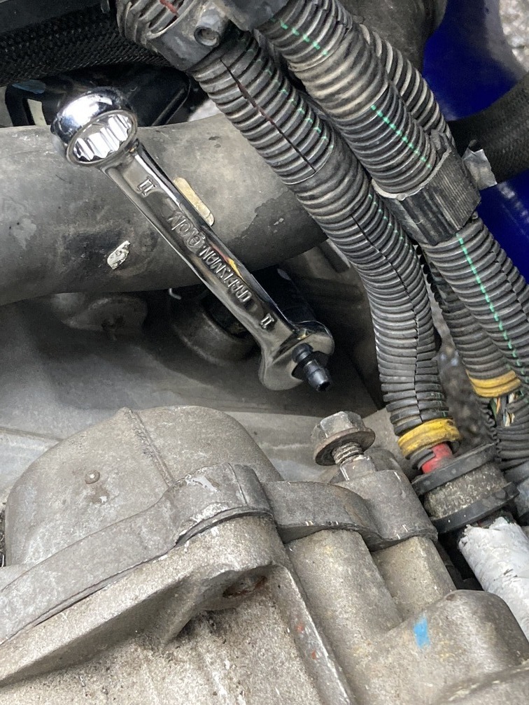
We started in the engine bay to remove the shift cable on the tranny housing. Locate the yellow capped end and you can pry this up and away from the retainer ball, releasing the end of the cable from the tranny.
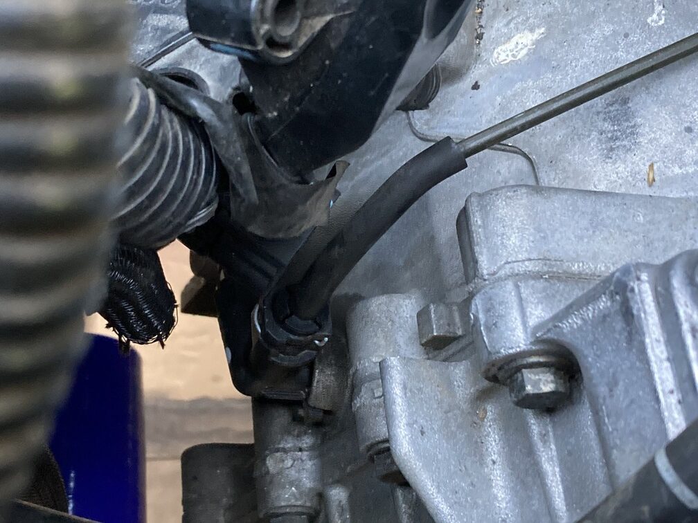
From there, move back along the line and you will find the cable bracket holding the cable to the mount with a half circle push lock, same thing here, pry up and release it.
We just snapped/broke the whole plastic assembly free. The m66 has different cable retainers, and they are metal, so we didn’t need to waste time trying to preserve this one.
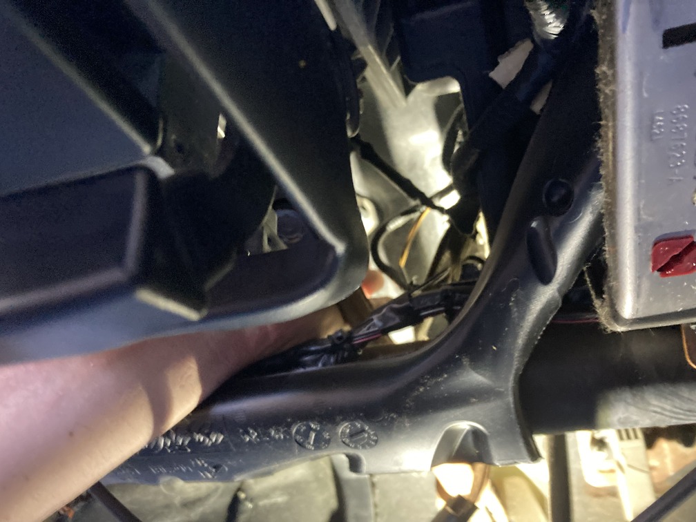
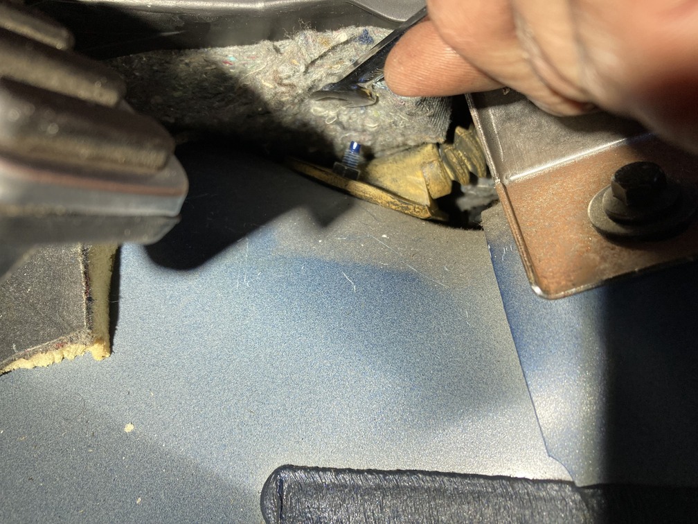
Last thing with the cable, under a heat shield on the firewall, is a metal retainer clip that the cable sits in. Pull down the firewall heat shield towards the front of the car, and reach down and pull the cable towards the floor, releasing it. Now the cable is free inside the engine bay.
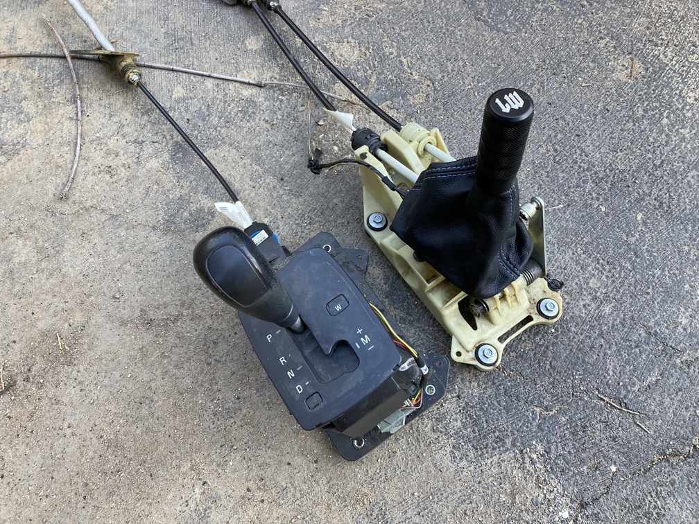
Next we move inside to remove the auto shift assembly. The mount is easy, one wire harness and four 8mm bolts.
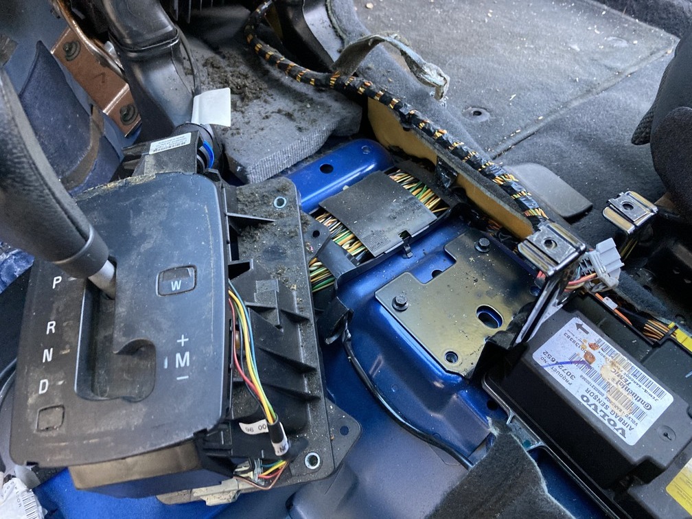
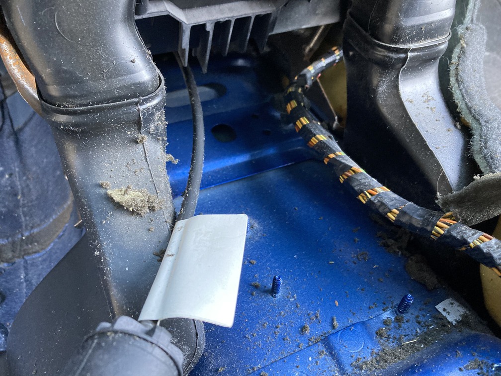
Now you have to fish the cable from the engine bay through into the cabin. First remove the firewall carpet under the cable. This is long and goes all the way back, ours came out in 3 pieces, but that’s fine as it will go back in to place no problem.
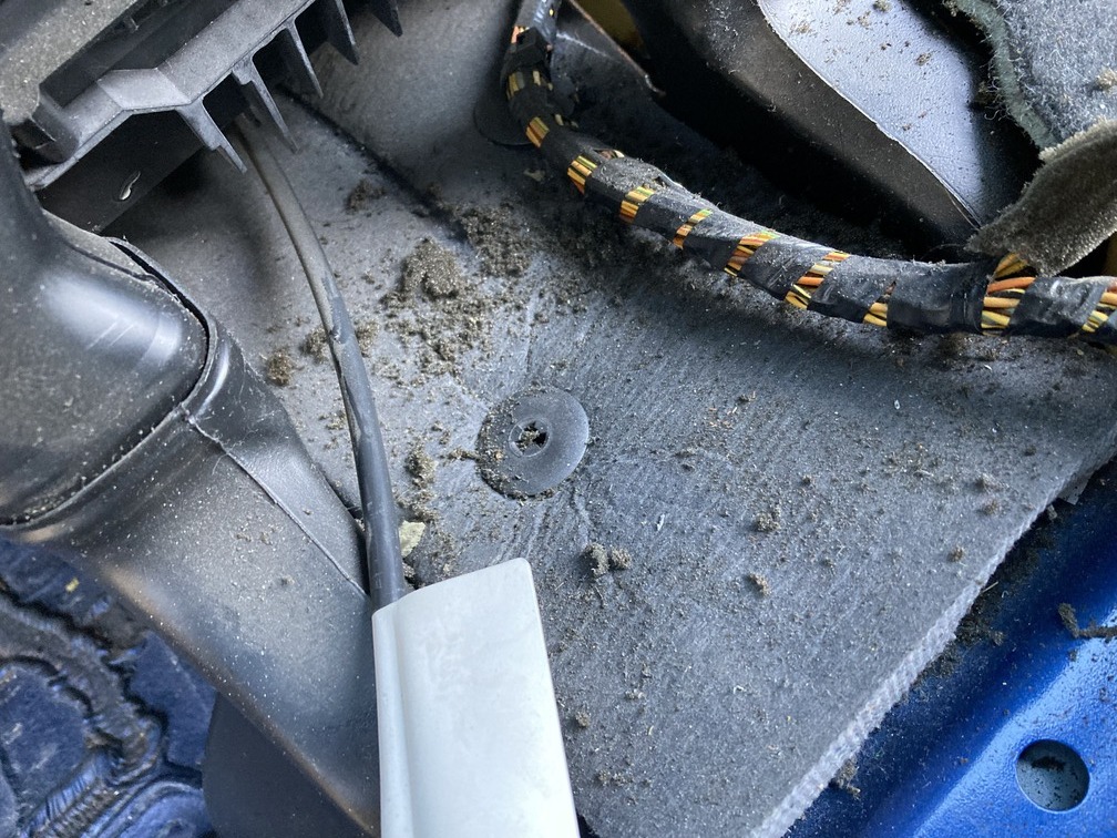
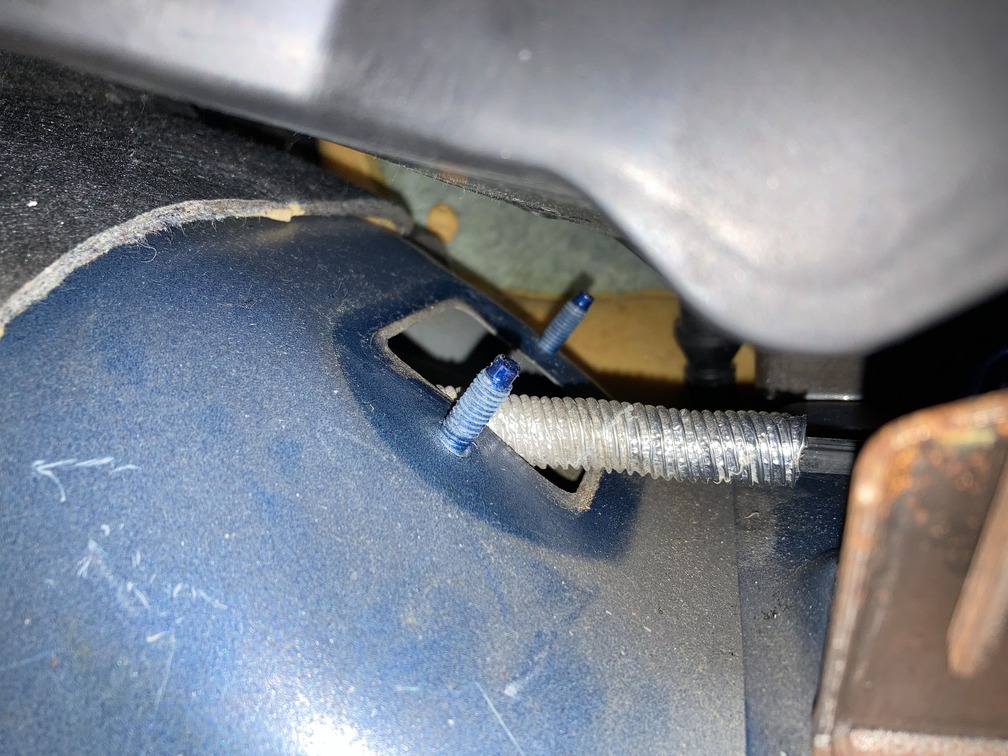
Now you have access to the 2 10mm nuts, that hold the rubber firewall cable retainer on. From each side of the cockpit, from the floor wells, get those nuts off, fully releasing anything holding the shifter assembly in place.
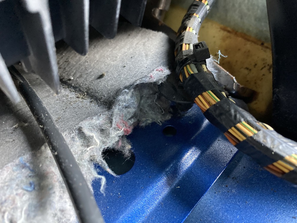
Now pull the assembly back into the car, and a hand in the engine bay to help push does help. Remember when the end of the cable comes the firewall hole, you will want to reach in from the side to angle it a bit to clear the firewall hole.
Then pull that thing out and toss it aside.
Next, you will reinstall the manual cable in reverse order. These bolts do have the same thread pitch, but they are 10mm. For one bolt under the cable, we used a swivel extension. There is no wire harness to attach here either, and fishing the cables, do that one at a time since they will not both fit at once.
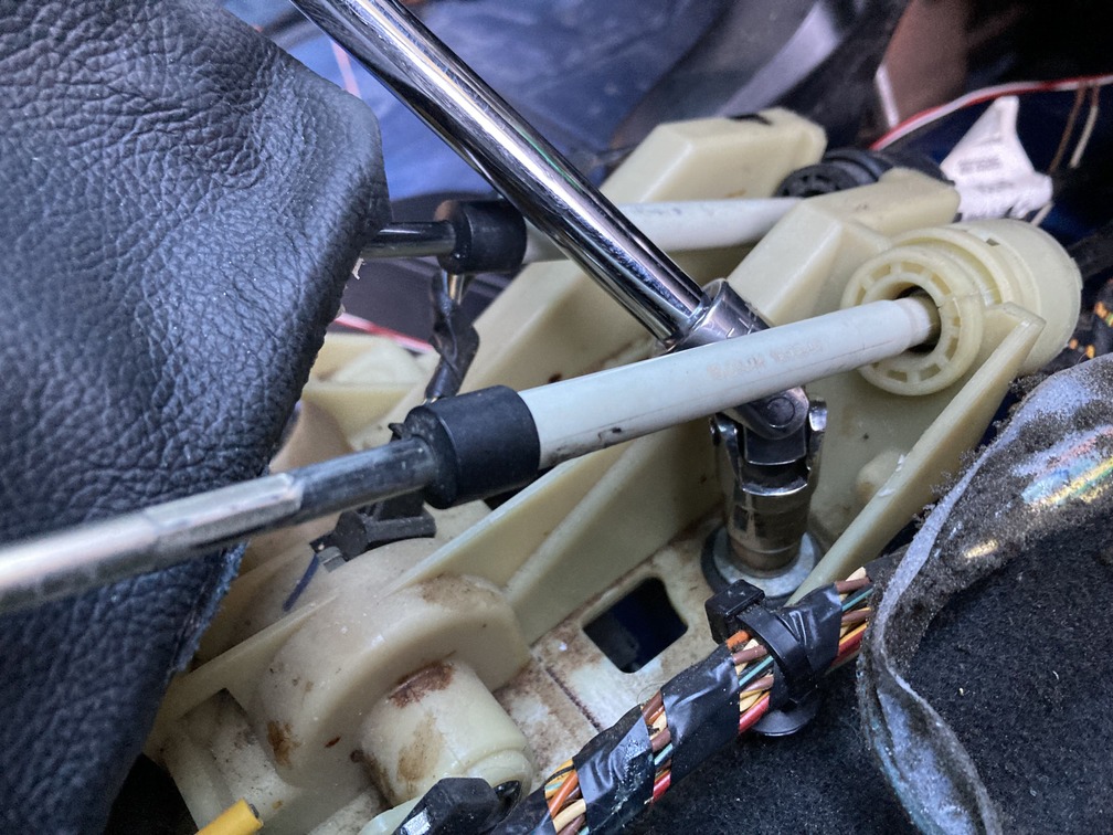
When you are done, you will have two cables hanging out above the tranny, and a new shifter assembly in place.
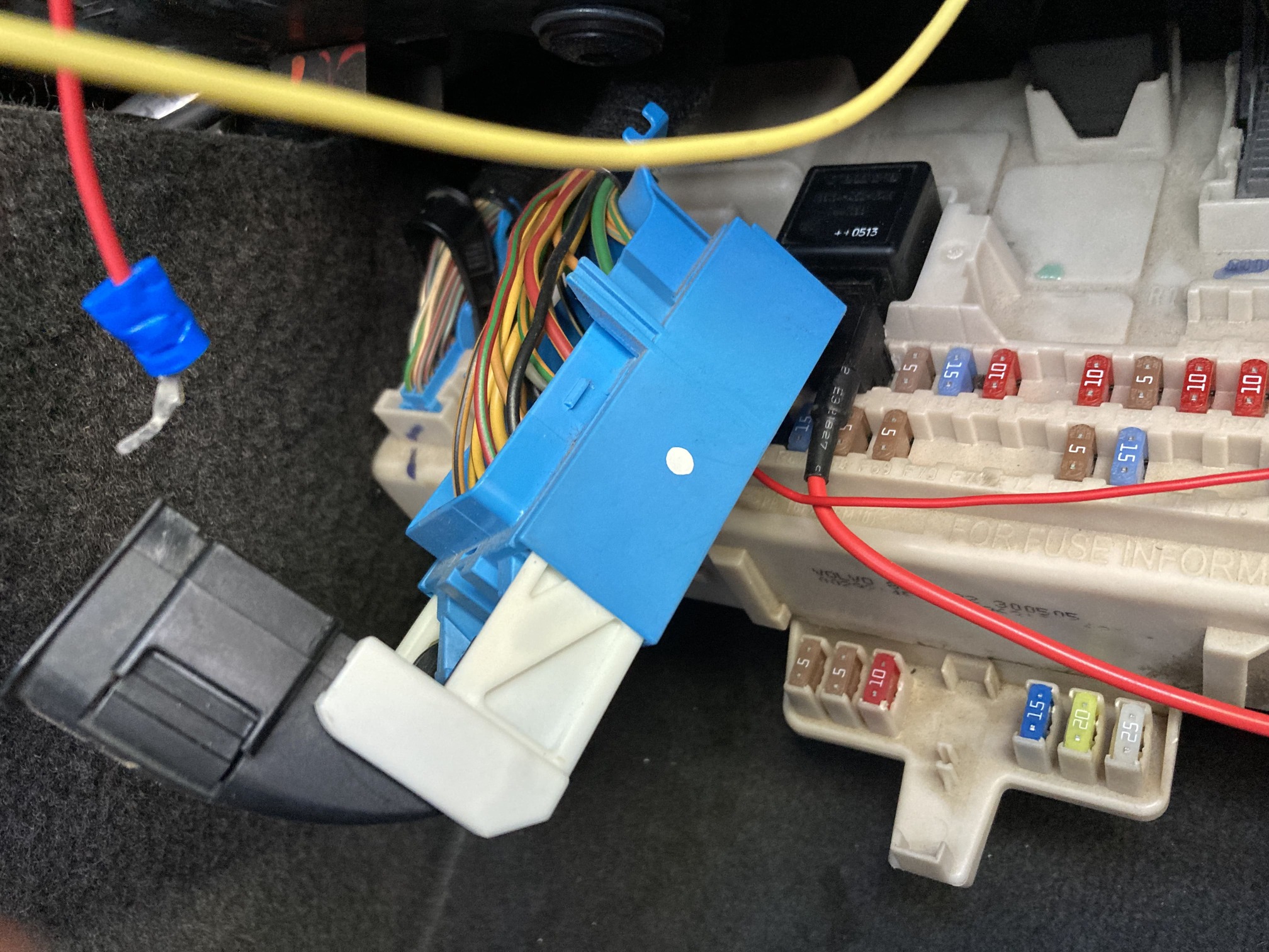
Oh yeah, since we haven’t finished researching the wiring for the reverse lockout, we ran 2 wires from the assembly through to where the ECU sits. They may wire there, maybe on the fuse box, no idea, but better to have some wires ran and ready.
Update: The two wires for the reverse lockout will go to the fuse panel under the passenger side glove box, so just have your wires left with the shifter and you will be good to go later.
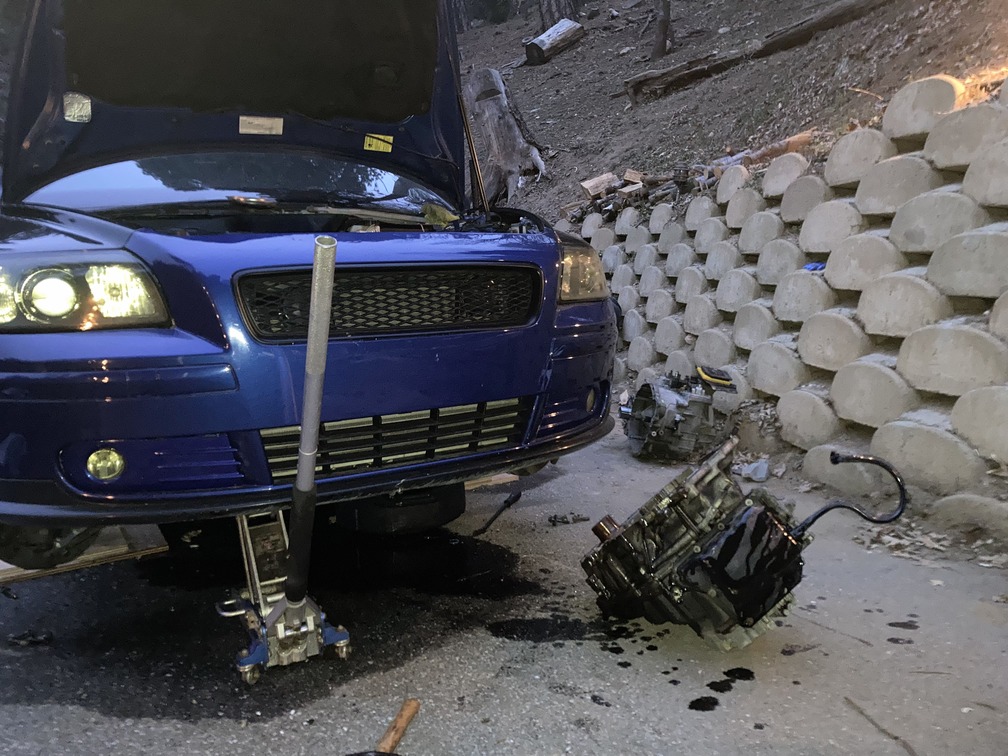
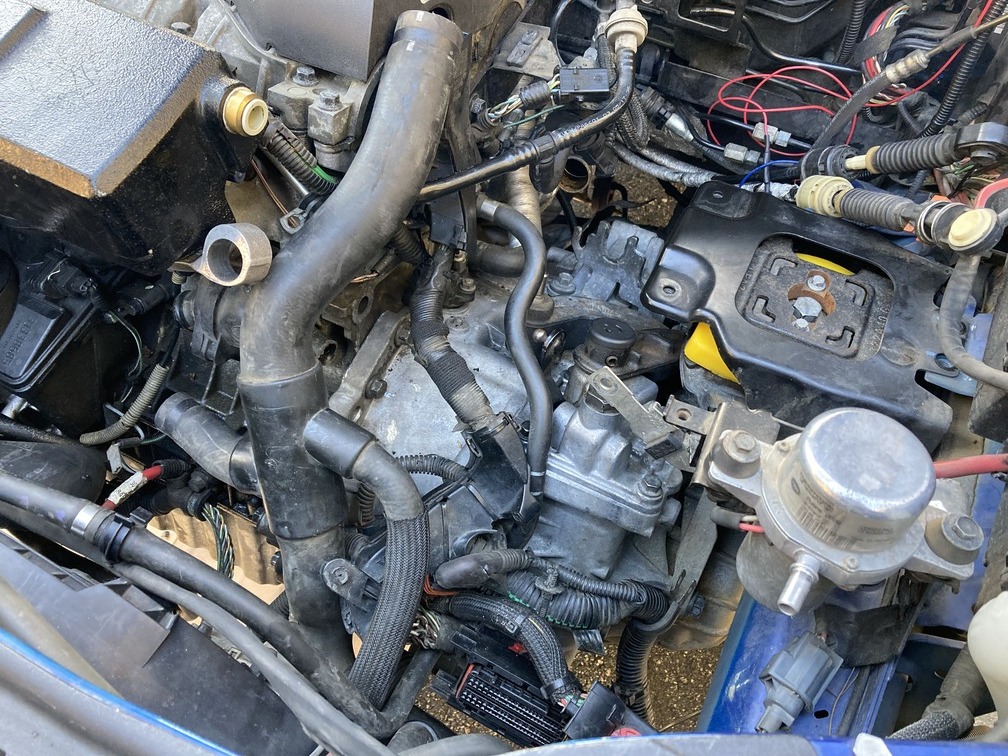
Day 4: Friday: Trans removal:
Now we already knew this was going to be the largest part of the take down. We did a casual 10 hours, but that was taking our time with breaks. We were also glad that a really solid video was already online, so we didn’t have to stop and document the process as in detail as the rest of the swap. We placed the video we followed below, but also have some notes for AWD cars, since the video was for FWD.
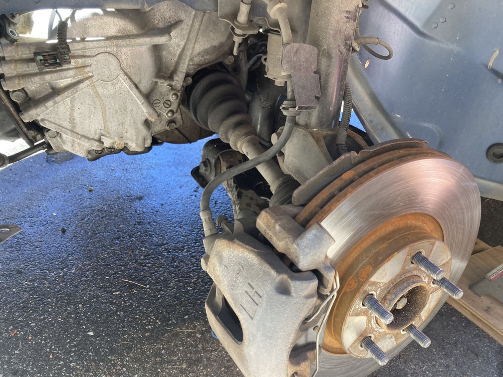
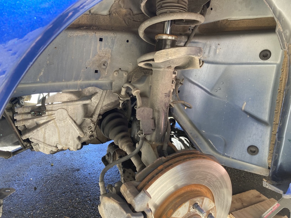
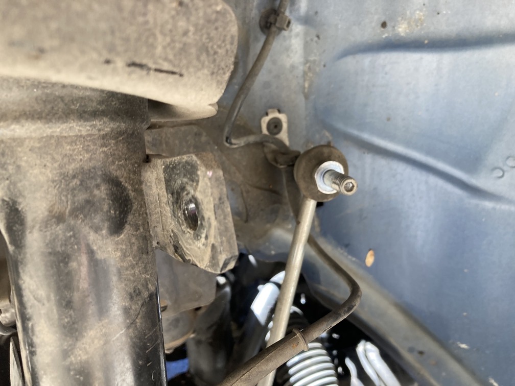
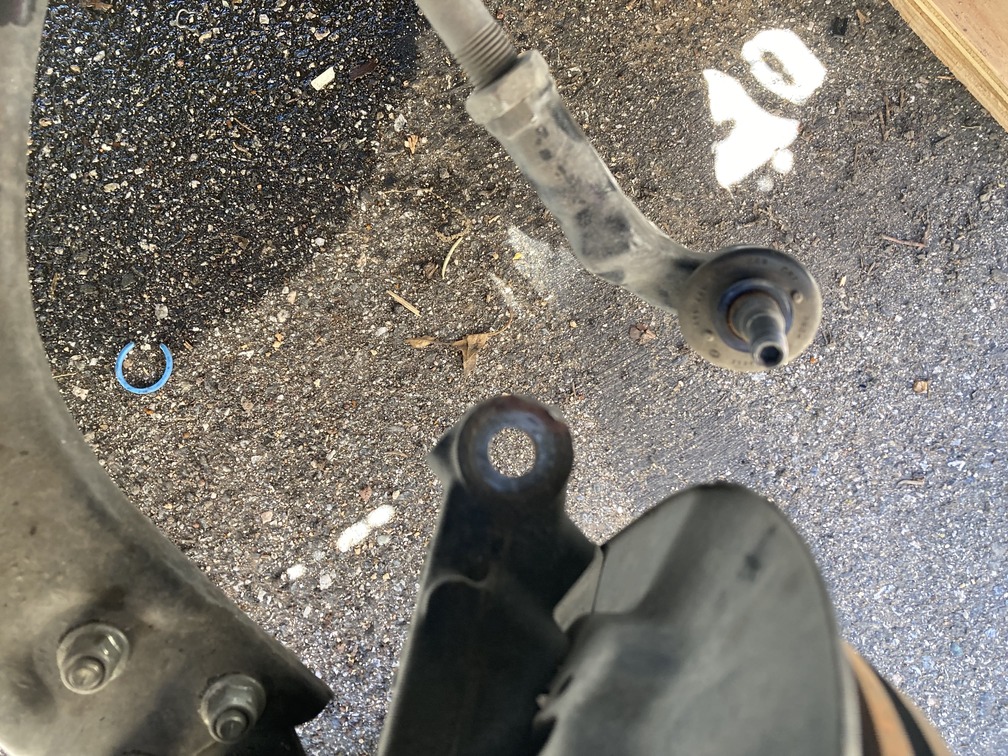
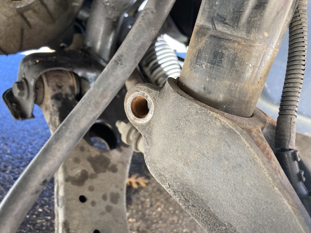
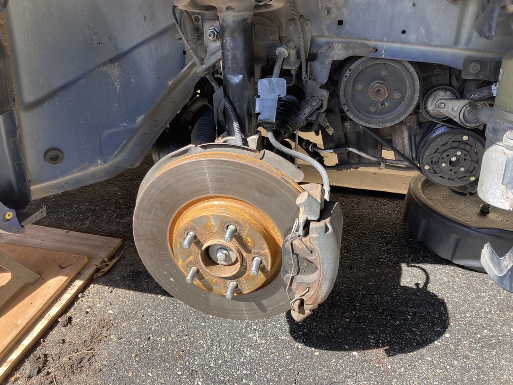
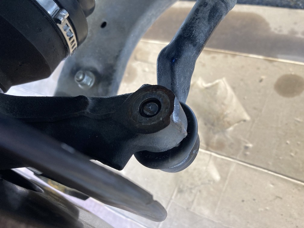
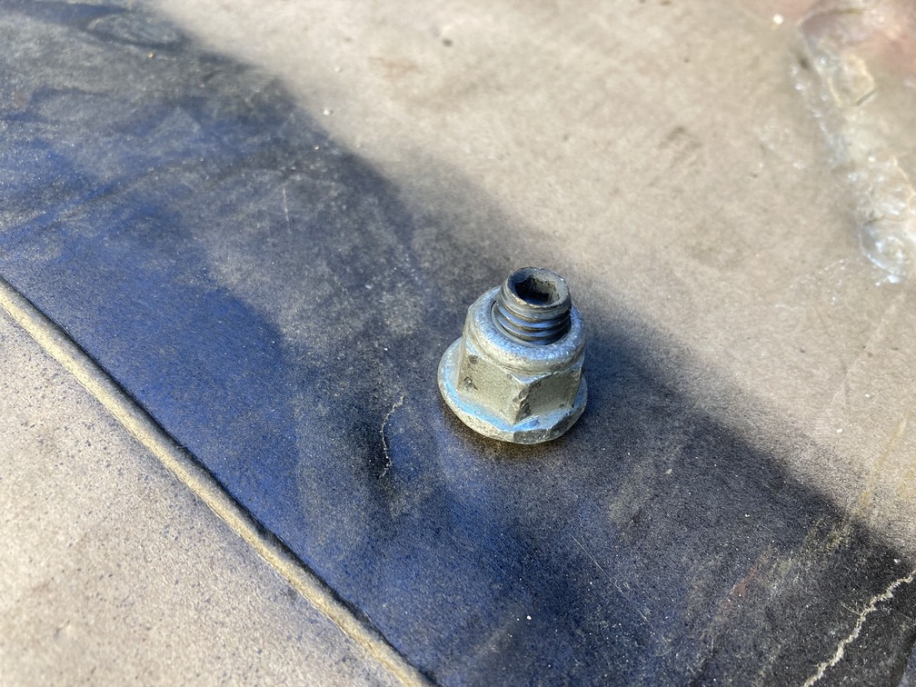
We start inside the wheel wells and removing suspension to get the axels out. Pull off the wheel well liner first. Remove the tie rod end nut, the control arm nut and the bolt holding the shock in the hub. This gives enough room to pull the axel. We pulled the hub assembly outward and turned, giving us room to pry out the axel after separating the clip ring on the tranny with a pry bar. For the passenger side, same thing, just remember there is a carrier bearing and bracket to remove as well.
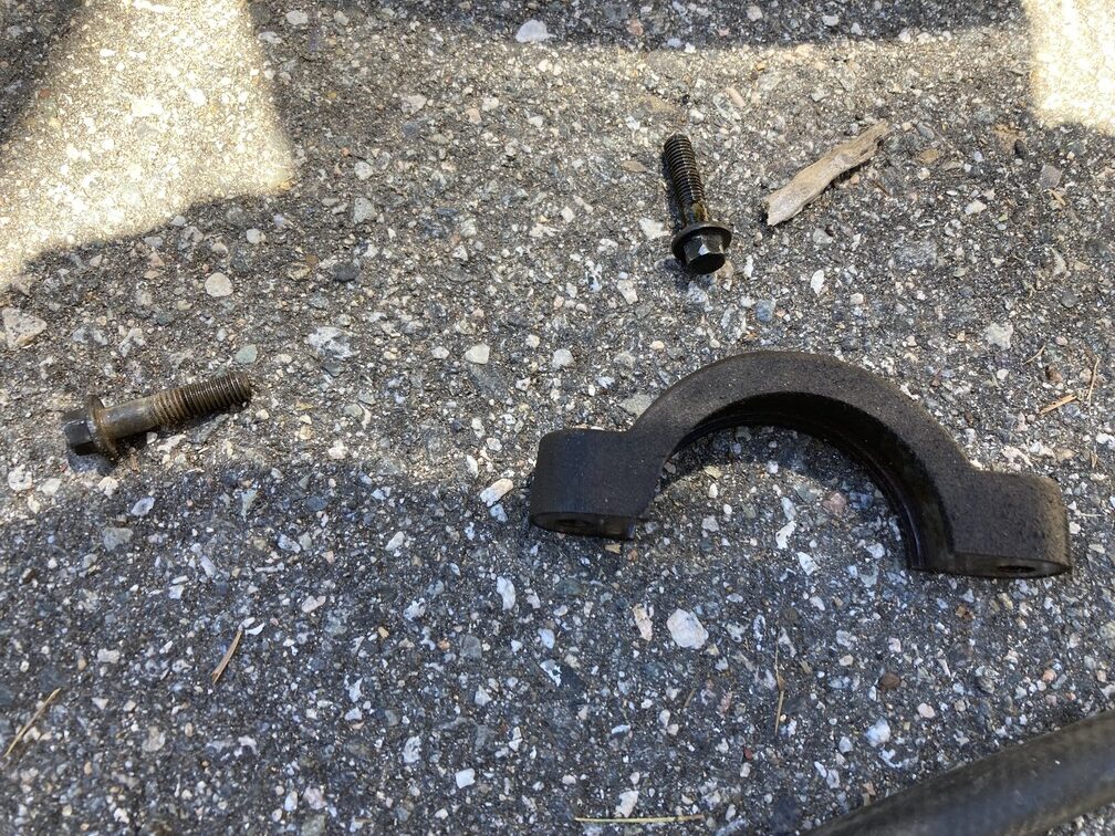
Next we hit the lower torque mount which was just a few bolts to remove.
From there we inserted our new Powerflex Poly Bushing insert (optional).
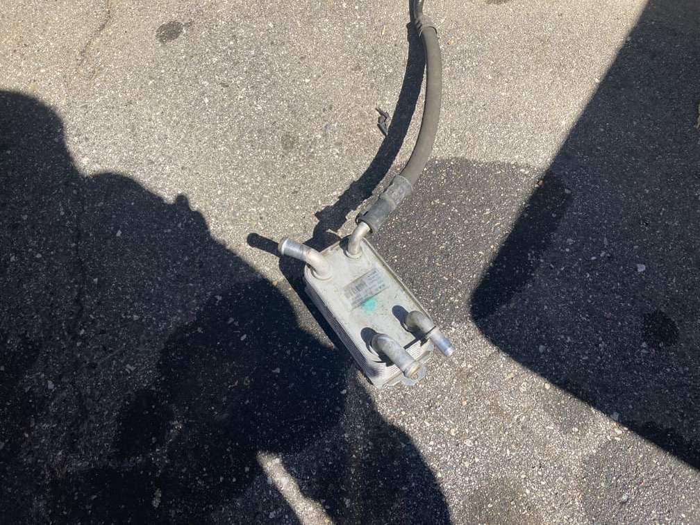
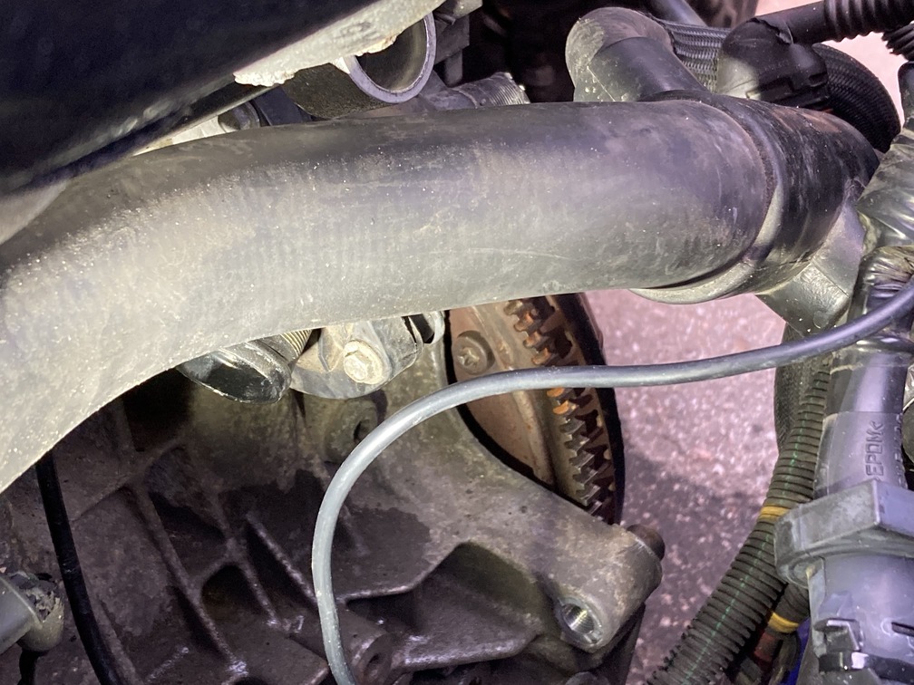
From there we went back up top and found a surprise we weren’t expecting with an external tranny fluid cooler. This simply has a line in and out for both coolant and tranny fluid. We disconnected the lines. We flushed out the tranny fluid side, and you can leave the unit installed for now without the tranny fluid lines connected and it will continue to loop coolant. We are going to remove the unit altogether and loop the lines.
This we found later, is a part we did not account for, and if you want, you can purchase and have ready the M66 version of the radiator coolant hose that does not loop through the unit. Here you can see the difference.
Manual Version:
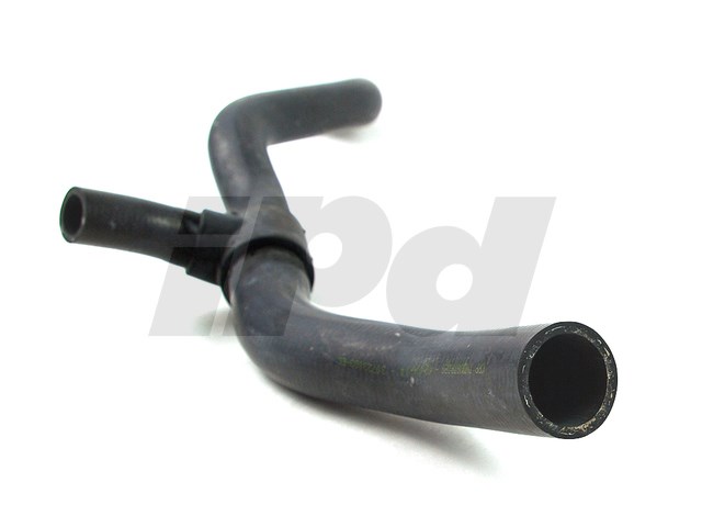
Auto Version:
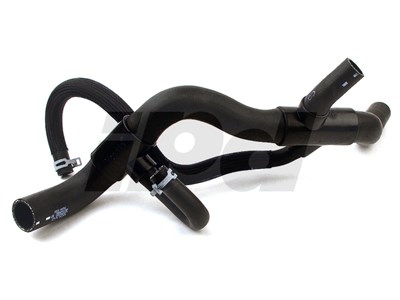
Auto hose number: 30723082
M66 hose number: 30723083
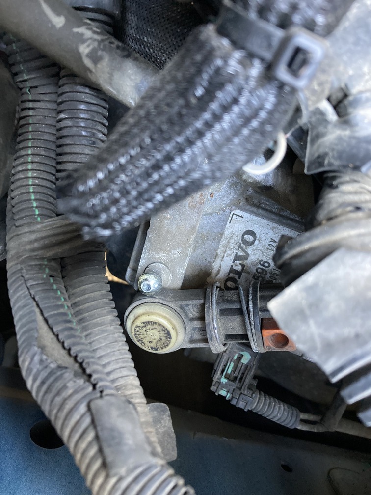
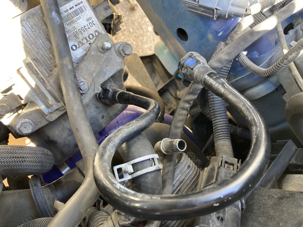
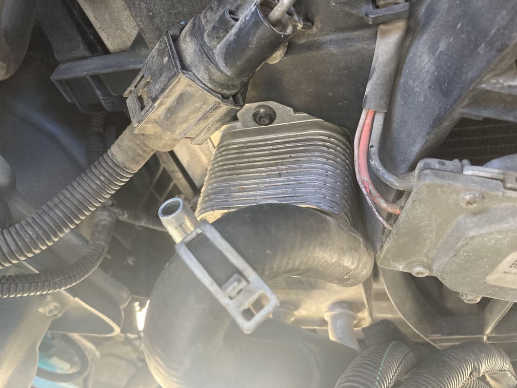
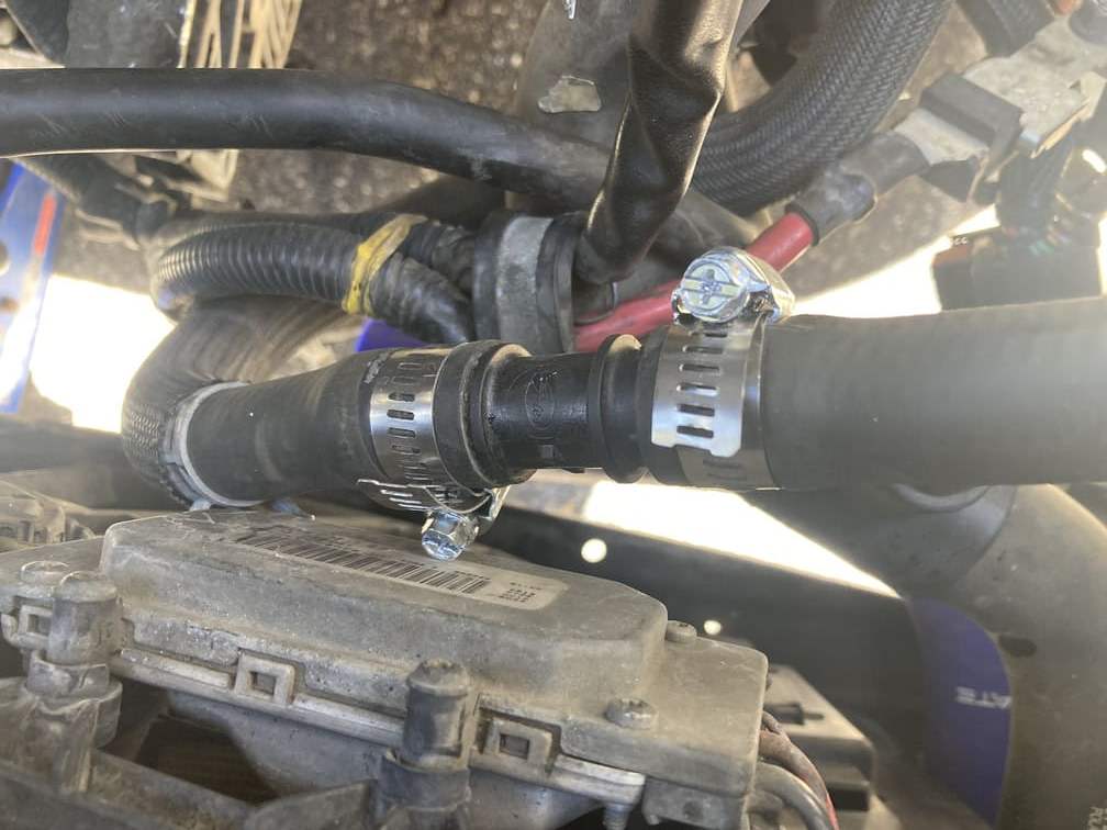
This unit is not used on the M66 transmission, so why leave extra weight on the car? The unit is behind the core support, on the driver side, next to the radiator fan. There are 4 lines running to it. This is a transmission oil feed and return, and a coolant feed and return. Since the auto tranny is out, you can pull the lines off that ran to the tranny (you may have already when you removed the auto tranny). From there you can either leave the unit in and connect the coolant lines back up later, or as we did, got a hose coupler and 2 new hose clamps and looped the lines together.
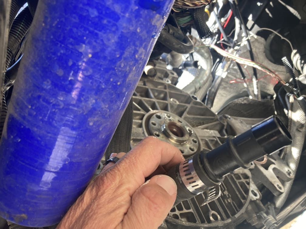
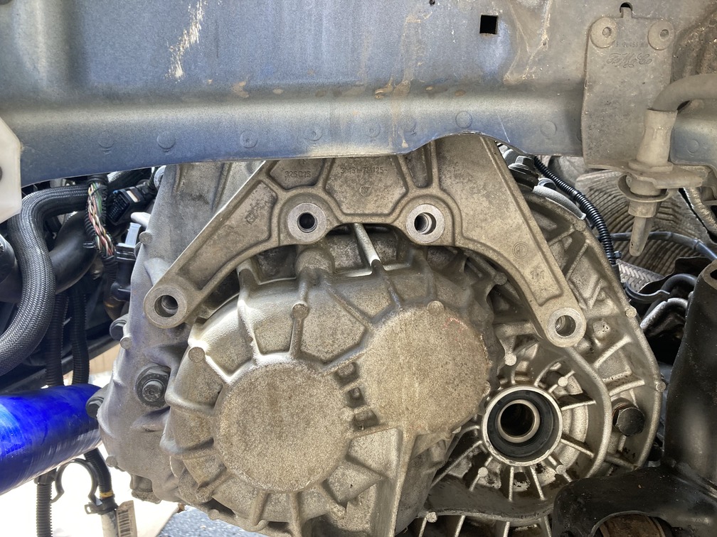
And then before referring to the video below, for AWD cars, you have to unbolt the angle gear from the tranny through the passenger side. This was pretty easy, just 4 bolts. Remove those and set them aside. When the tranny slides out the angle gear will stay in place.
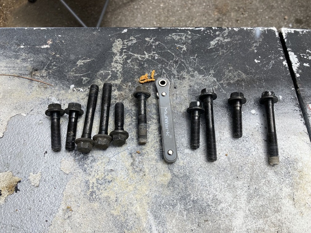
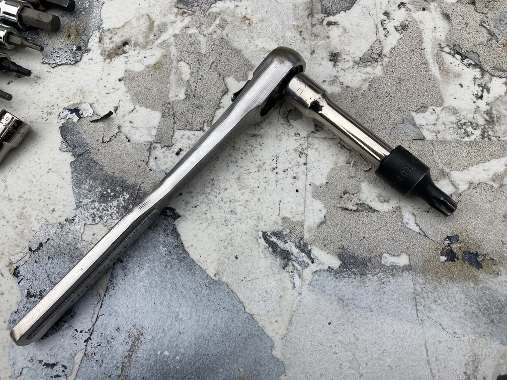
For reference, here are the bolts in order, for the tranny, Starting at the vehicle speed sensor at 12o’clock TDC tranny and working counter clockwise. This way you have a layout for where the bolts go back in. The small ratcheting wrench in the middle represents the longest bolt on the bottom of the tranny, which would not come out until the tranny was off. It was so long that once all the threads were off, the head of the bolt was backed against the engine block.
And then a whole day later…
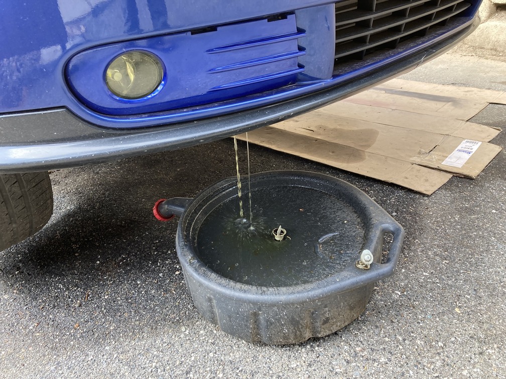
Pro Tip: Drain the tranny fluid first, as you can see, we did not, and dumped it all on the driveway.
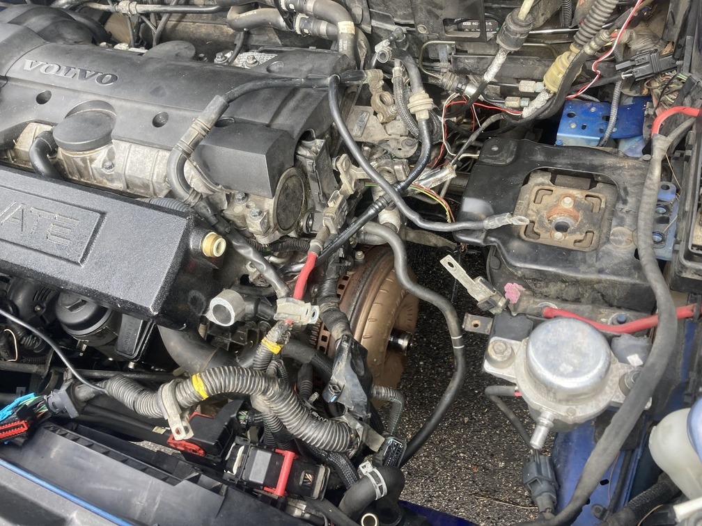
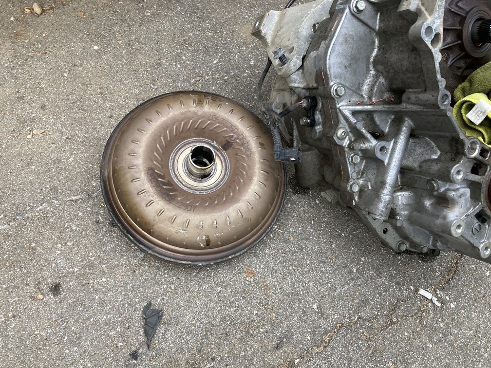
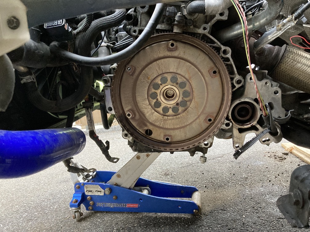
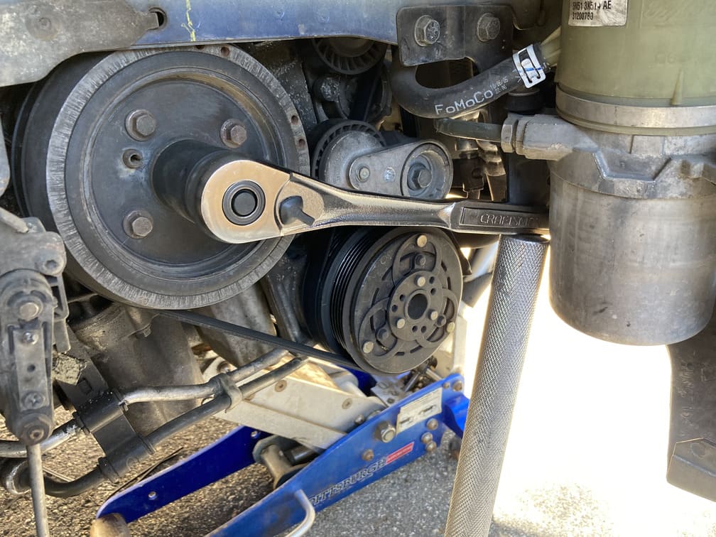
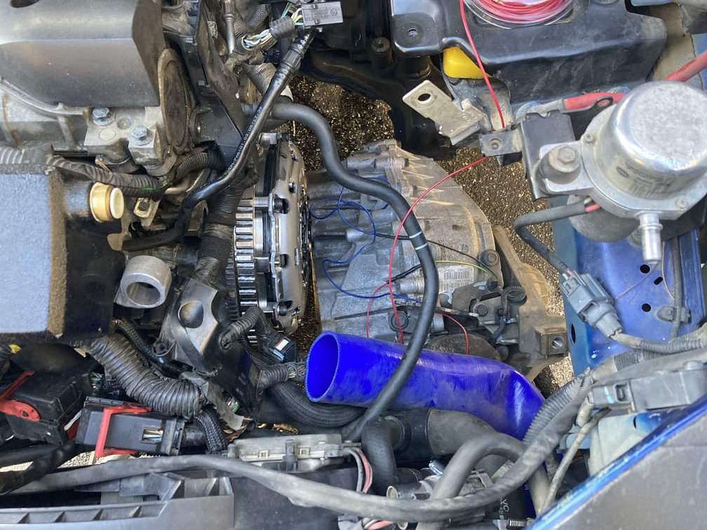
Day 5: Monday: Torque Converter and Flywheel Removal:
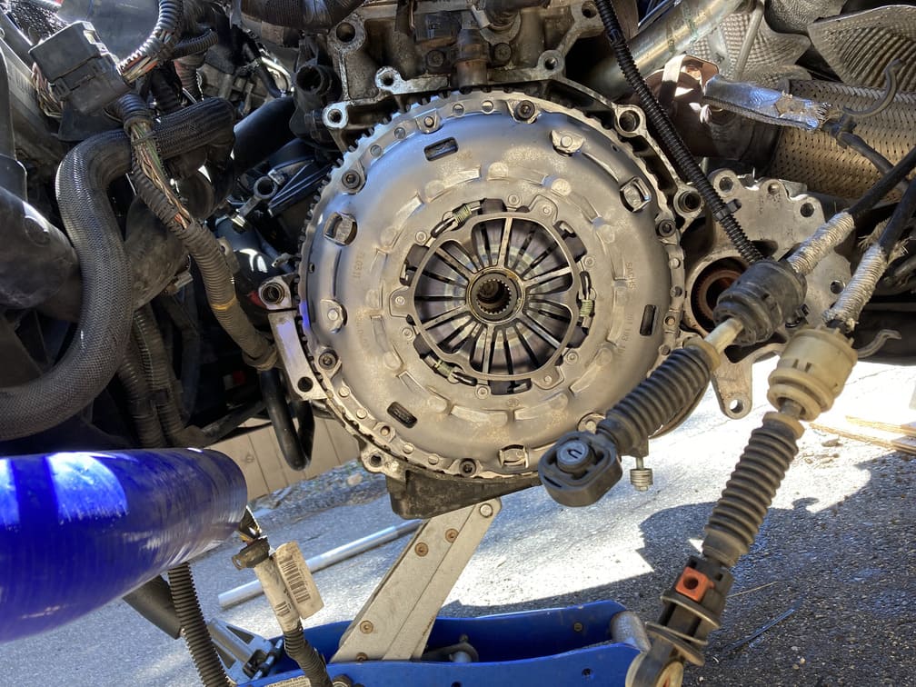
Easy day planned, just get the torque converter and flywheel off. Here you can see the torque converter attached to the engine block via the flywheel.
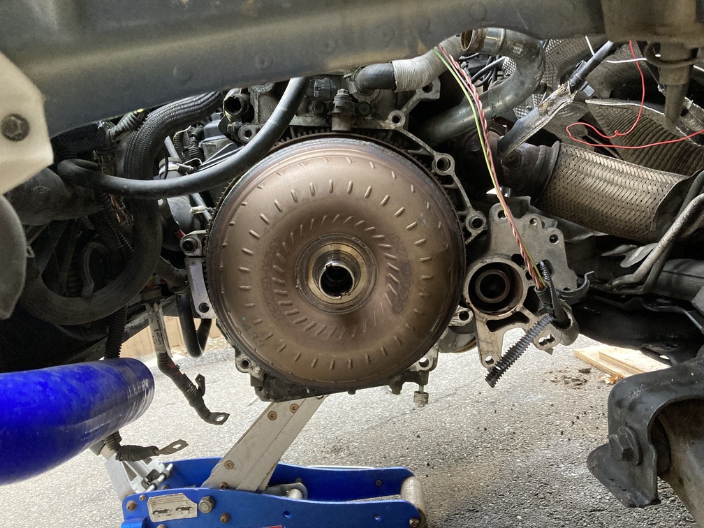
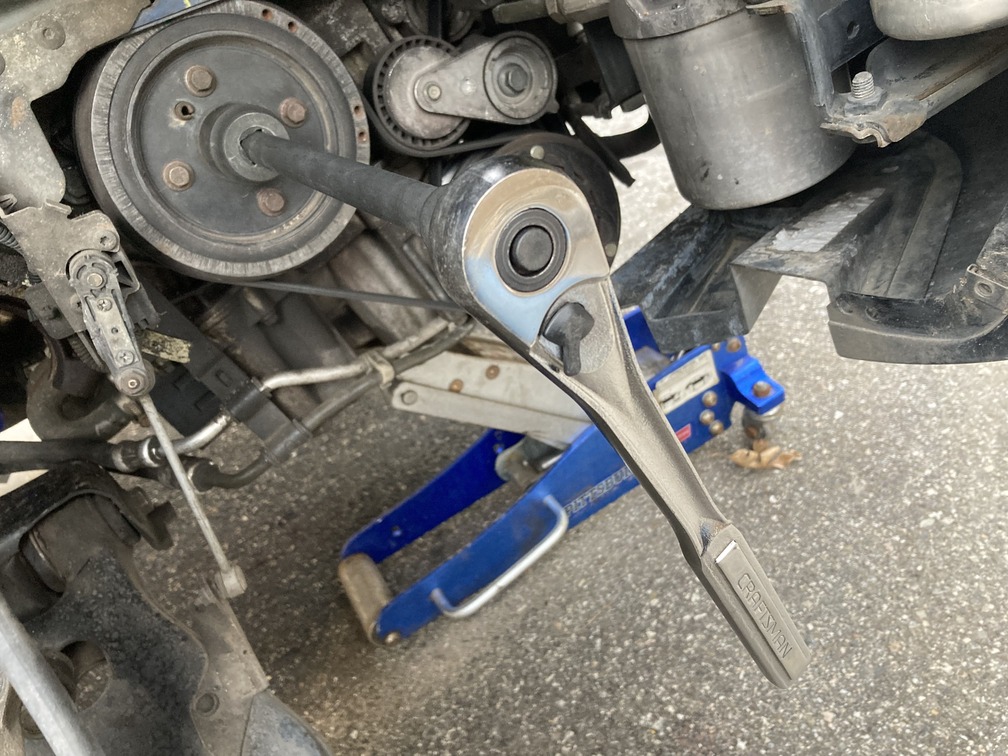
There are 6 bolts, T50 Torque head holding the torque converter to the flywheel. These are bolted in on the back of the flywheel. Here you need to also have a 30mm socket and ratchet available to spin the crank. There is a small notched out section on the engine block that allows you to access those bolts one at a time. After removing one, turn the crank clockwise to access the next, and repeat until all 6 bolts are off. From there you can pry the torque converter off of the flywheel.
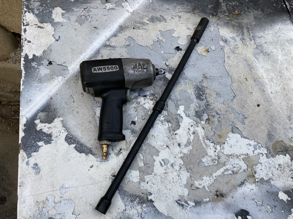
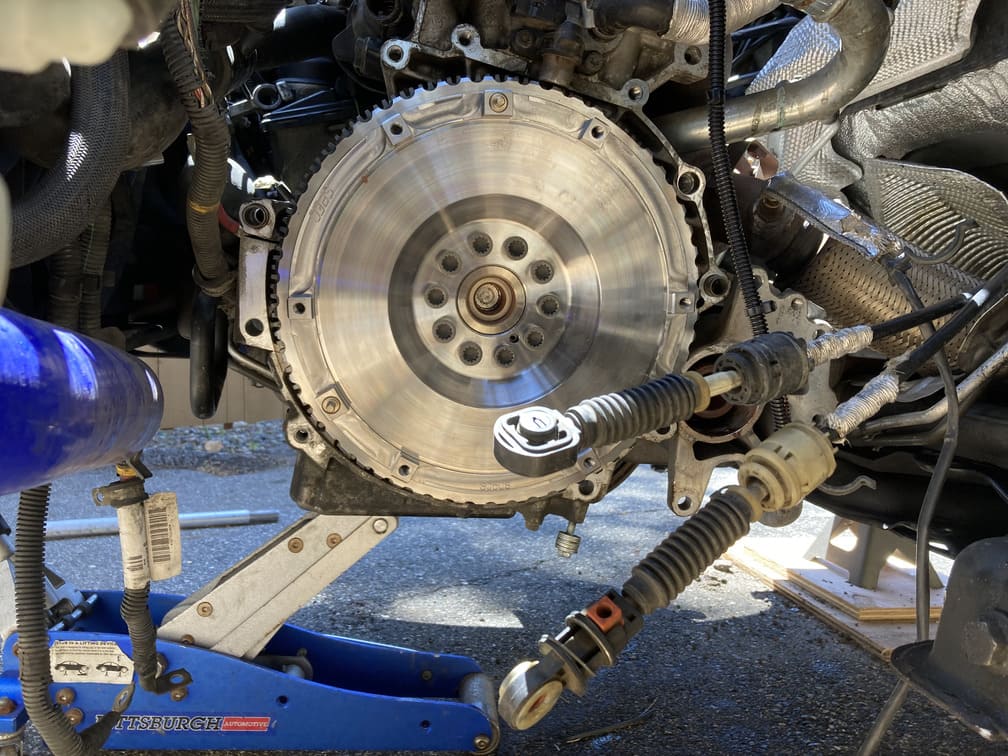
Last piece of the automatic transmission set up to remove is the flywheel. Here you will have 10, 17mm 12 point bolts holding the flywheel to the engine. We used air to get these off.
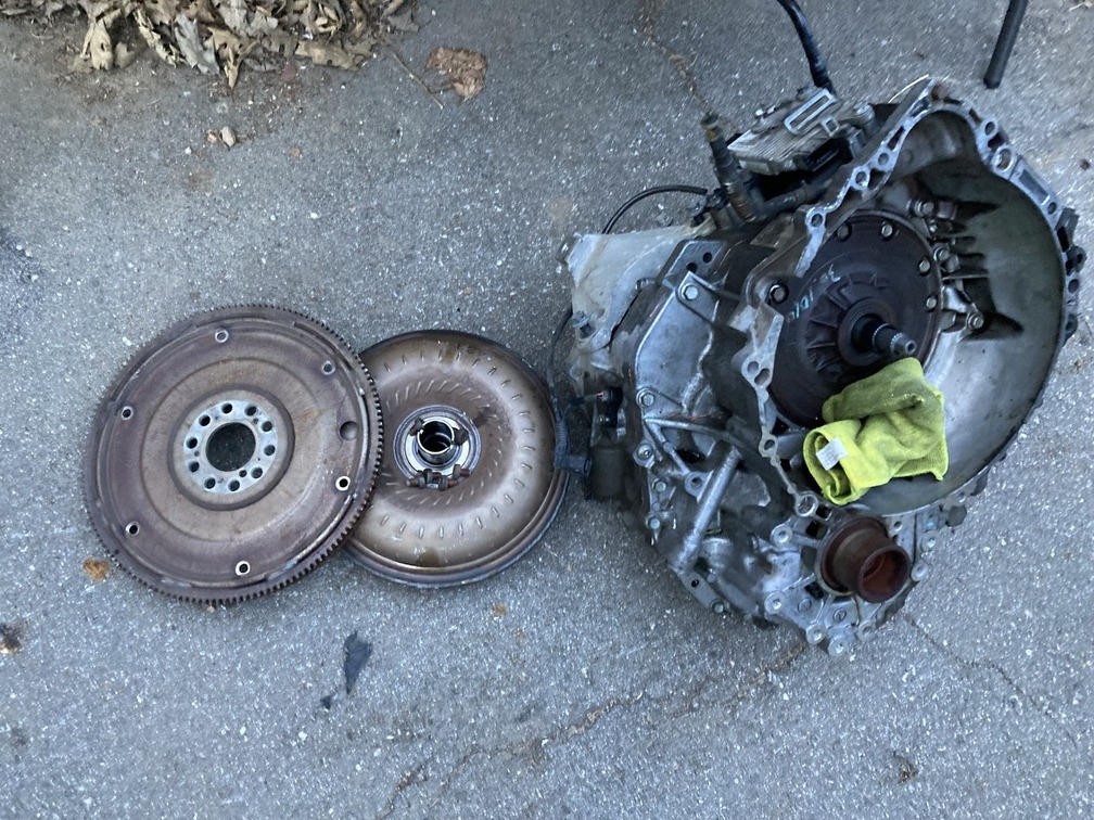
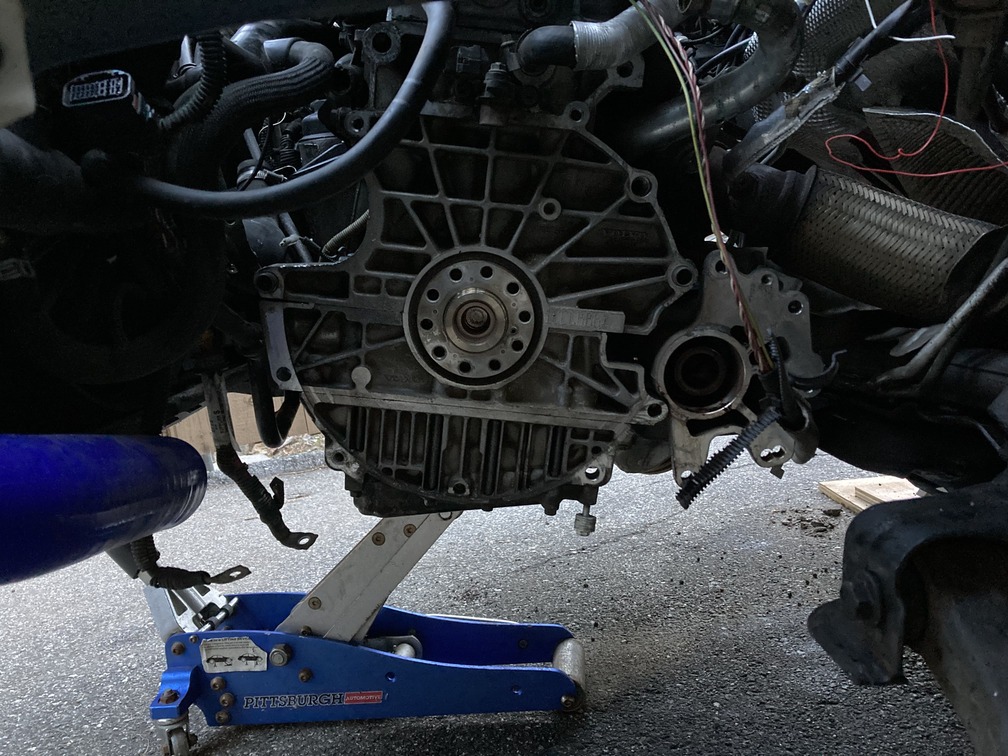
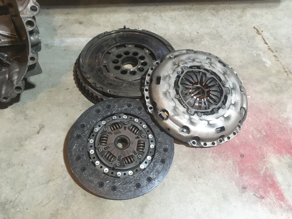
Day 6 – Tuesday: Flywheel, clutch and pressure plate installation.
Now the fun part, with everything auto gone, we start building the car back up in manual mode.
We start with the new Spec single mass flywheel we got from Viva. It did not come with bolts so we had ordered brand new ones from IPD. You can also use your old ones, but be sure to add new thread lock on them to seal the threads since those holes can leak engine oil. The new bolts have the thread lock already on them. At this point, while the flywheel was off, we removed the pressure plate bolts and set them aside with the pressure plate.
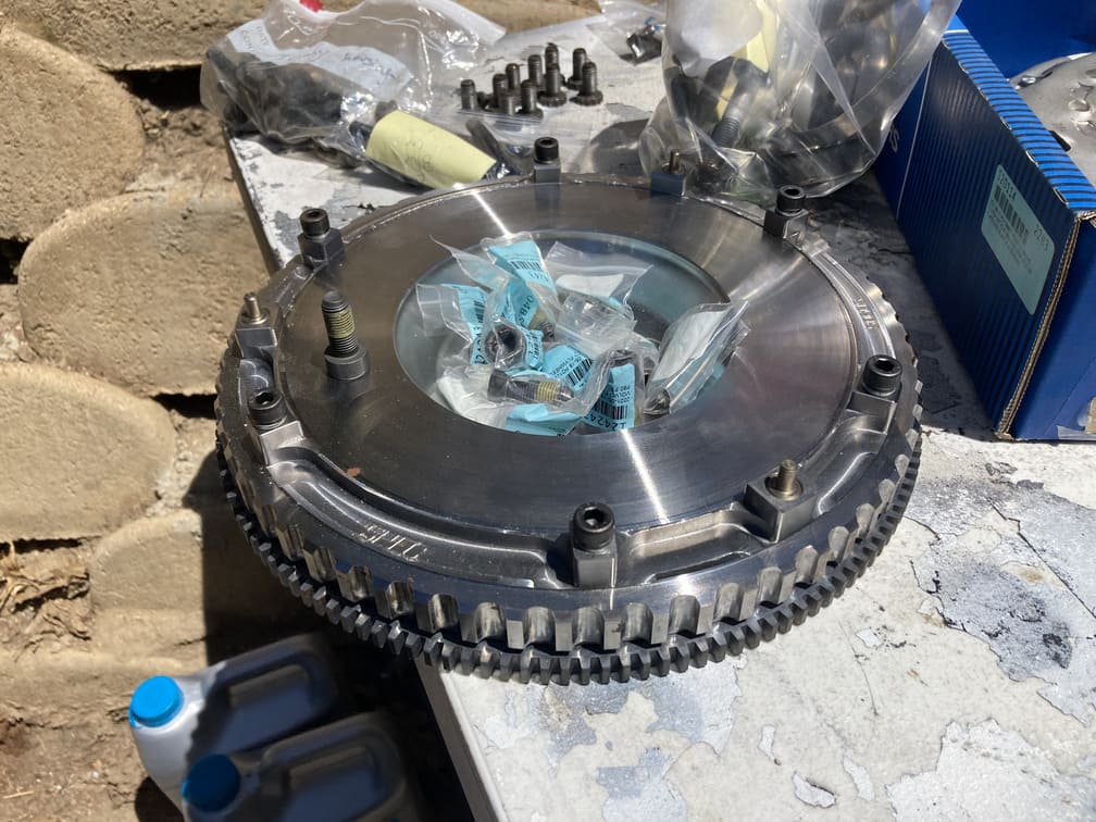
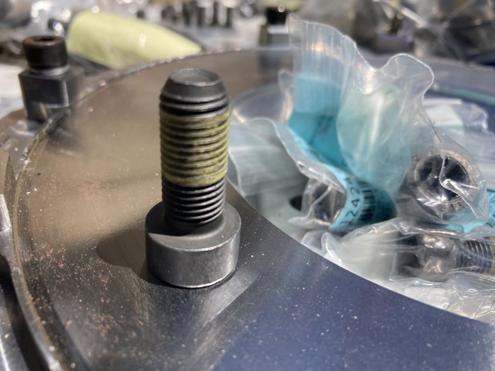
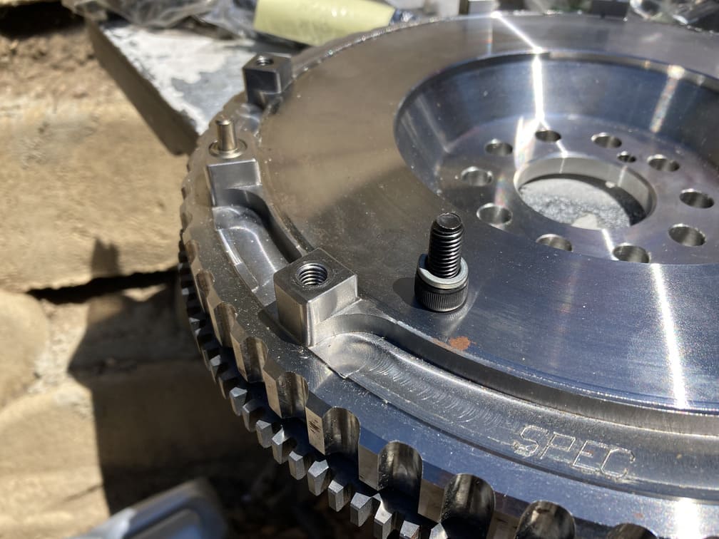
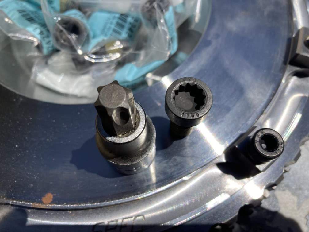
The new flywheel bolts are T55 12 point, but we have a 6 point and it fits safe enough for the torque spec required.
We place our 30mm crank socket and ratchet on the crank and lock it into the power steering bracket. Since those are metal and thick, they will hold up to our torque on the flywheel and prevent the engine from spinning.
We put the 10 bolts in and go around the clock going hand tight. From there the spec is as follows:
First Pass: 45nm/33lbsft – we went around skipping every other, then went around again on the other 6. Then a final loop to ensure everyone was at spec.
Second Pass: 65 Degrees – here we started with our ratchet pointing straight to the ground. We then pulled it towards us until it was at about 9 o’clock, a dead 45 degrees. Then we reset and did less than half of that pull for the remaining 20 degrees, put the ratchet pointing just past 7o’clock. We did this all around every other bolt, then offset and went again.
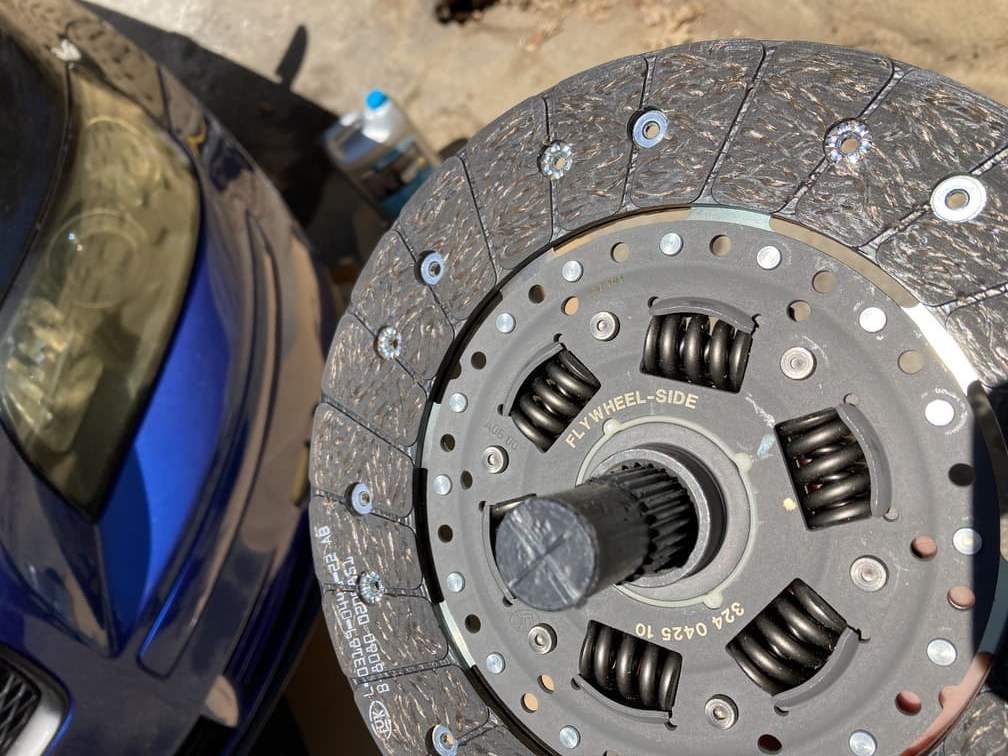
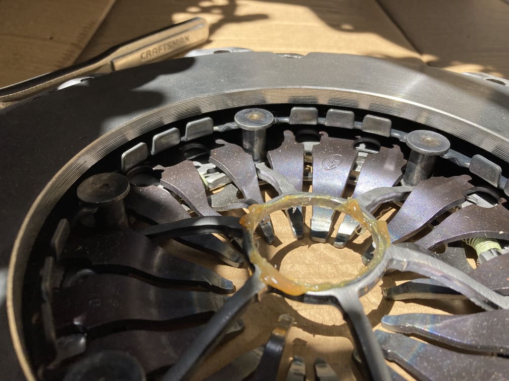
Next up is the clutch. We grab that and the clutch retainer tool (plastic tube). If you are new to manual, this tool will hold the clutch in place while you bolt the pressure plate around it, then it can be pulled out. Pay attention to orientation. On the clutch should be printed a direction for placement, which we see here “flywheel side”, meaning there is a right and wrong way to place this.
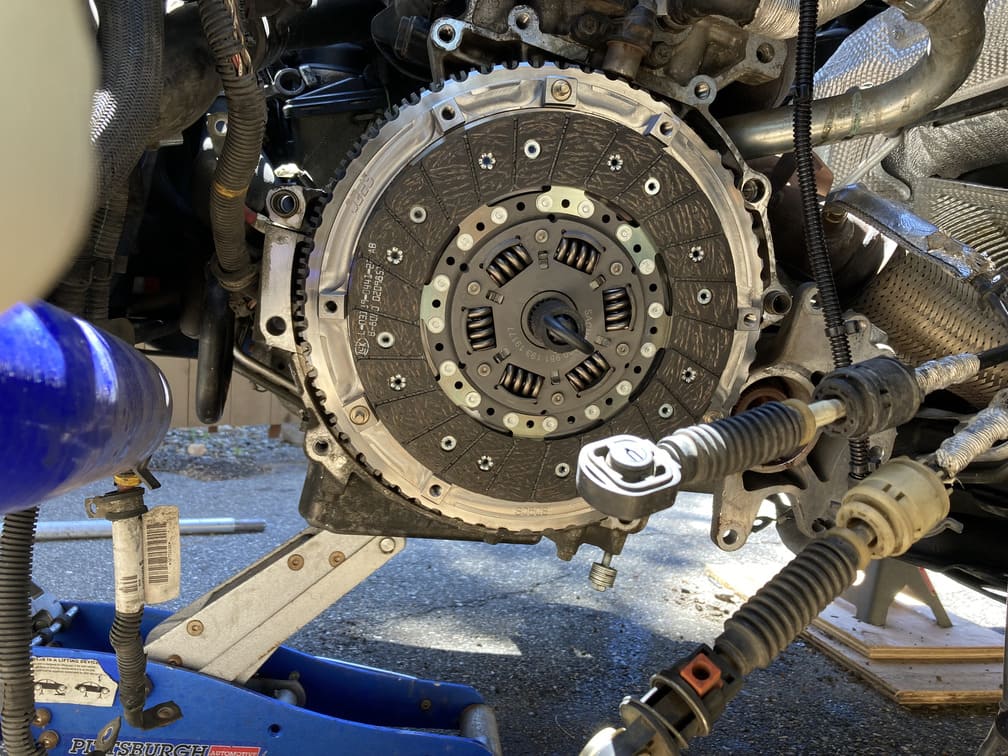
Now time for the pressure plate. First we used the supplied grease to lube up the center where it will rotate. Next place it onto the pins on the flywheel and then place the 6 allen blots (6mm) to secure it in place. You will see a gap, but as you tighten the bolts it will pull itself flush. From there torque those to 18lbsft and then remove the clutch retainer tool.
Done. We had some extra time, so we also decided to swap out the top tranny mount with our newly assembled one with the poly bushings.
And with a few more minutes, we spliced in some wires for the reverse sensor. Having these is place now is easier than trying to splice with the tranny in the engine bay, and will come in handy later when we get to the wiring portion. Also we started to get the tranny in position to go up.
Day 7 – Wednesday: Get That Tranny In!!!
Won’t bore anyone with the details, but a lot of jacking and moving around, took a few hours to get this thing seated. Probably a bit easier for FWD vehicles as lining up the engine splines and the AWD angle gear at the same time was not fun.
Important note, for clearance, we did remove the tranny mount to get it up into place, and then replaced after we had a few bolts in place.
After we got all the bolts in, we tightened them all up and moved onto the lower tranny torque mount.
From there we hooked up our shift linkage and clutch lines. Those all just pop into place.
Day 8 – Thursday: Engine Bay Back Together – Tranny Fluid Fill – Back on the Ground and then Coolant flush
This was easy enough, just get all your wiring harnesses and lines back in place. We later took off the battery and the bottom intake filter to get access for bleeding the clutch line. So you can also leave those off at this step, or take them back off later.

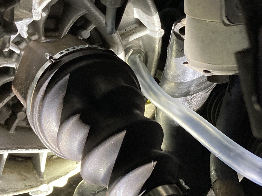
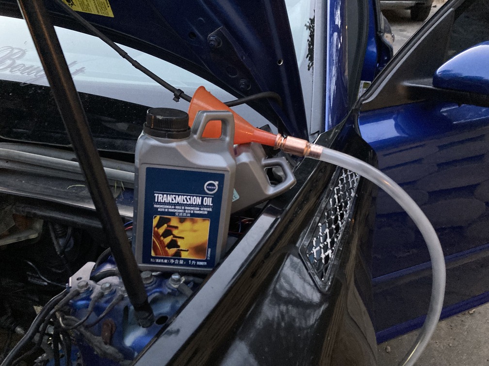
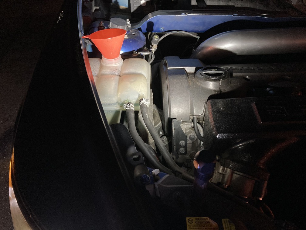
Here we bought a clear fill pipe from the local auto parts store, and simply jammed it into the tranny fill hole, and then poured two liters into the funnel up top. It does require a tad more, so we cracked open the third and poured until it start coming back out. From there quickly pull the tube and replace with the fill plug.
Here we just reassembled the axles and all that good stuff. Put the wheel wells back on and then all the suspension bolts.
We ran into an issue and snapped a tie rod, but the local parts store had one to us same day.
While we had some time, we dropped the lower radiator plug. We had lost almost half the fluid anyways, so we decided drop it all for a fresh fill.
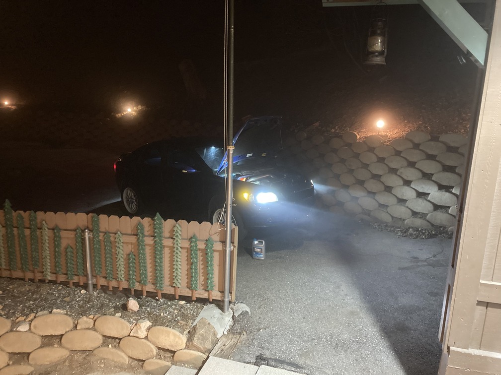
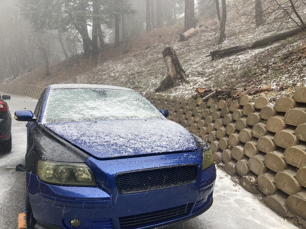
We were keeping momentum regardless of the rain and 35 degree temp.
Day 9,10,11,12- Friday-Monday: Clutch Line Bleeding, Problems and Solutions
Friday: Now up to this point everything was going smooth. We figured at some point we would run into some problem, and have to stall out and source parts, and this is where it happened.
Fellow ImportSauce team member Derek rolled up for the day to assist, and while the weather was looking to clear about mid day, it continued to snow and it was in the low 30s with wind.
It all started as planned, pull the brake reservoir cap and top off fluid. From there one person in the car pumping and holding pedal, then me under the hood opening the line to release air, and then closing the line while the pedal is depressed. Then repeat. We did this for what seemed like 2 hours. Every time I opened the bleeder, a pssst of air released and I assumed we were slowly pushing fluid down to the throw-out bearing.
After hours of not getting fluid, I wanted to check the lines, and bingo… I didn’t hook the clutch pedal to the brake reservoir. I remember I was going to wait until bleed time to make sure I didn’t have fluid flowing into parts that were not secured or ready.
We then pulled the bottom cap off the brake reservoir (same reservoir for auto and manual, just the auto version has a plug cap), and quickly attached the clutch hose.
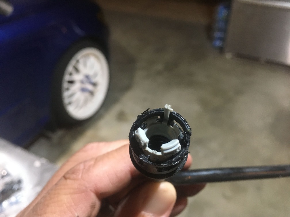
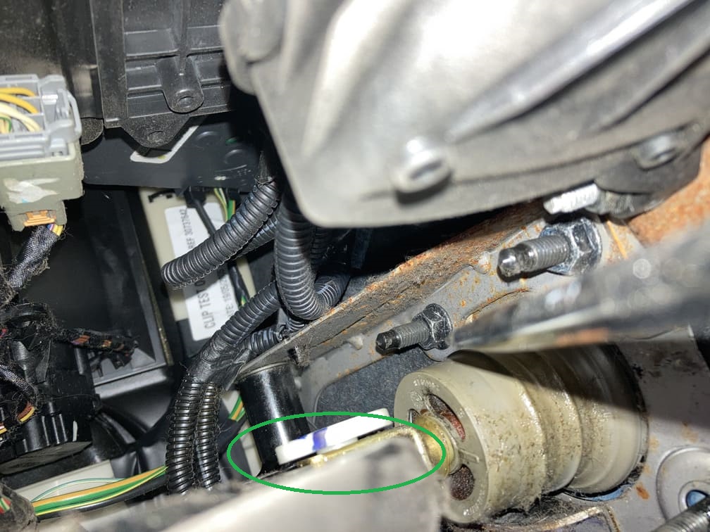
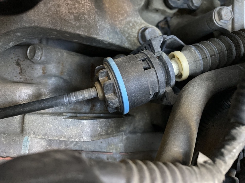
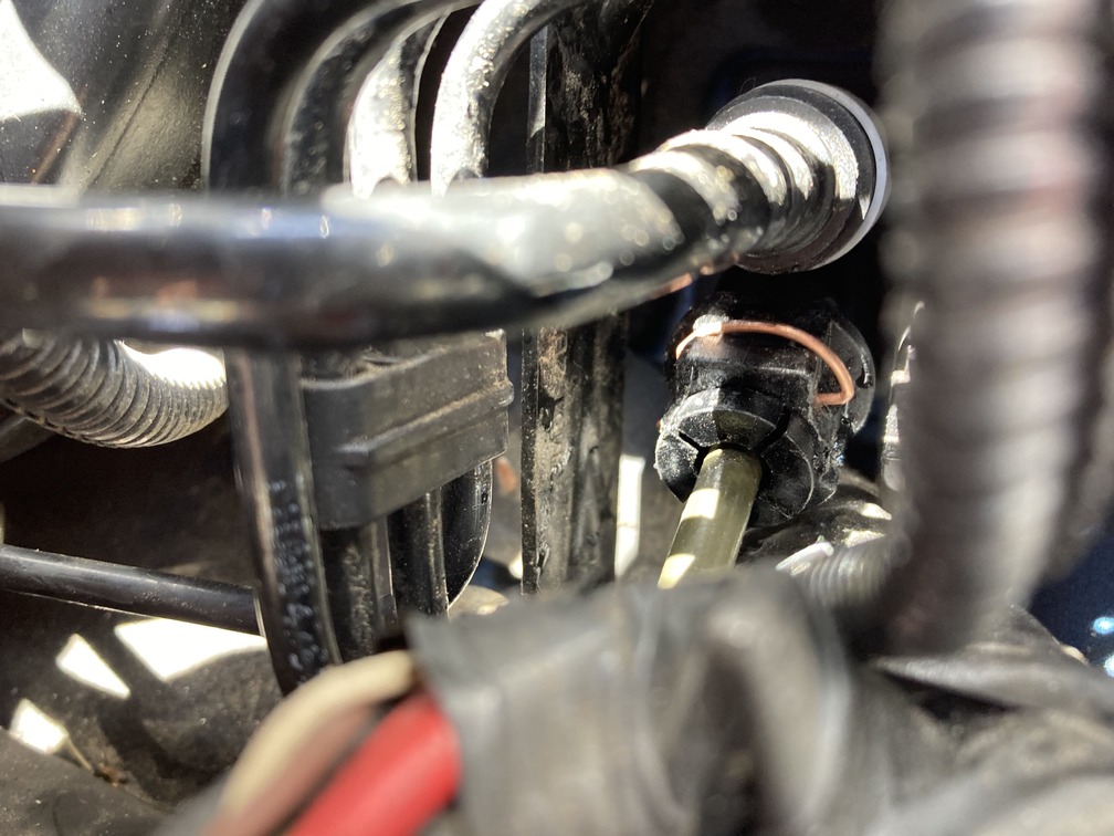
With new found hope, we started the bleed again. After about 5 pump sessions, we hear a pop… surprised and confused, we chalked it up to “air bubbles” forcing out of the clutch pedal. We continued on for a while and assumed we were good since now actual fluid was slowing sputtering out the bleeder valve. After another hour or two we realized something was wrong. After inspection, we then noticed that the hydraulic hose from the tranny to the clutch pedal had popped free from the master clutch cylinder. Not all the way off, but enough to suck air in. This was due to a bad retainer clip. We messed with the clip, tried to bend and reshape for it to hold, but a gentle tug would pop the hose off every time. At this point we could not feel our toes or fingers and it was 9:30pm, so we called it a night and started in on some beers.
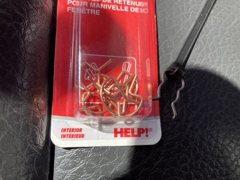
The thought was to try and source a new retainer clip at the local parts store in the morning and hope we didn’t have to special order the clip from Volvo and wait days. For reference I would recommend getting all new retainer clips before starting. While the new master did have one, removing the hose even once can damage it. You would think these things don’t take much shelf space, but Volvo does not have these in stock and it is a 2-3 day order to pick up at the dealer, add a few more days shipping if you want it delivered.
For the extra $10, having a backup set of these clips is recommend. It is the same clip for the hydraulic hose where it meets the master, the intermediate line and where it meets the bleeder, so grab 3.
Lock Clip: Part Number: 8636353
Saturday: Off to the local parts store to see if they have some kind of clip that would help out here. Ideally Volvo part would be great, but that’s hours drive and wait time, surely the local parts store has something.
After searching the doorman section, the best thing we found was a door handle crank retainer clip, but the pinch points matched perfectly despite the shape being different.
and it snapped into place, and after trying our hardest to pull the hose out, it was locked in solid. We have ordered the Volvo clip and will replace when it comes in, but for now this gets the bleed process back on tract.
Without a pedal pusher, I was done for the day and in hopes I would have an assistant at some point, and then later in the day a buddy called needing to grab some tools from the house, so I invited him over and then had him hop in for bleeding round 3.
Same process as before, but this time we had clutch pedal pressure in about 10 minutes. We continued on and bled until foamy bubbles were gone and a steady stream of fluids was coming through. Time for a test drive.
Now remember we did not have the flash on the the CEM, so we were getting a handful a codes from the car, but it fired up and was drivable. Most codes were related to the auto transmission since the car still thought we had one.
We went for a 10 minute test drive and all seemed to be good. Got it back home and as soon as we pull into the driveway, the clutch pedal goes all the way to the floor and no clutch!!! We assumed it was just needing a new bleed since now driving with clutch and brake, the fluid was moving back and forth through the lines.
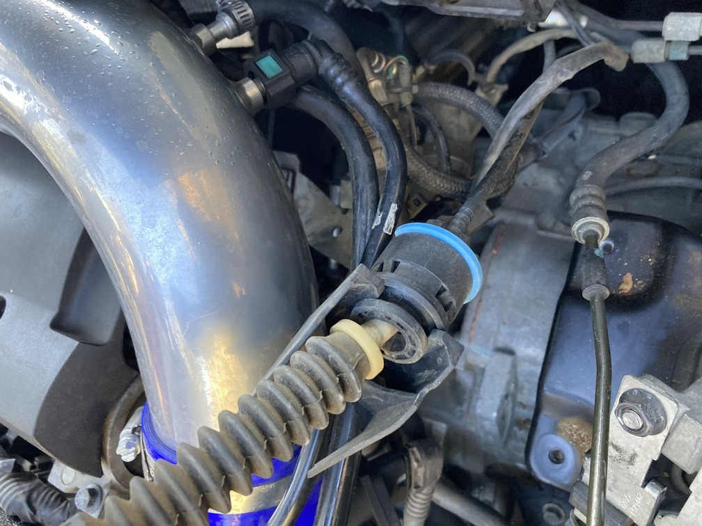
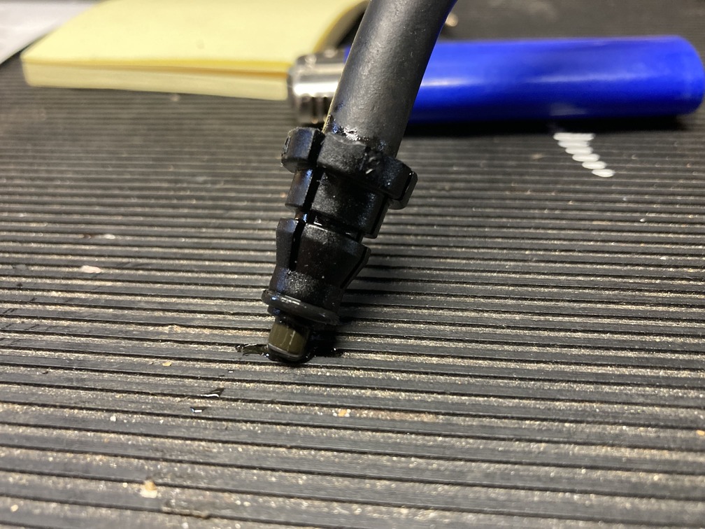
From here we initiated the bleed again, but I started noticing some fluid seeping from the bleeder to hydraulic hose area. After closer inspection we realized every time we held the clutch pedal down, fluid would seep out. Hmmmmm…. We had a brand new o-ring on this coupler, but went to our box of o-ring assortment and decided to go with one the same internal diameter, but a bit thicker. We popped that on and bled again… same issue, then we tried other o-rings, bled again and same issue. Over and over trying different configurations. At this point the bleeder valve was wearing out and starting to strip, it is plastic after all. We ordered a new one to place on at a later date.
At this point we called it and decided I would try and track down a new o-ring, or just buy the entire hose from Volvo. This is the one part we used from the donor, and maybe after all the coupler on the end was worn down or misshaped.
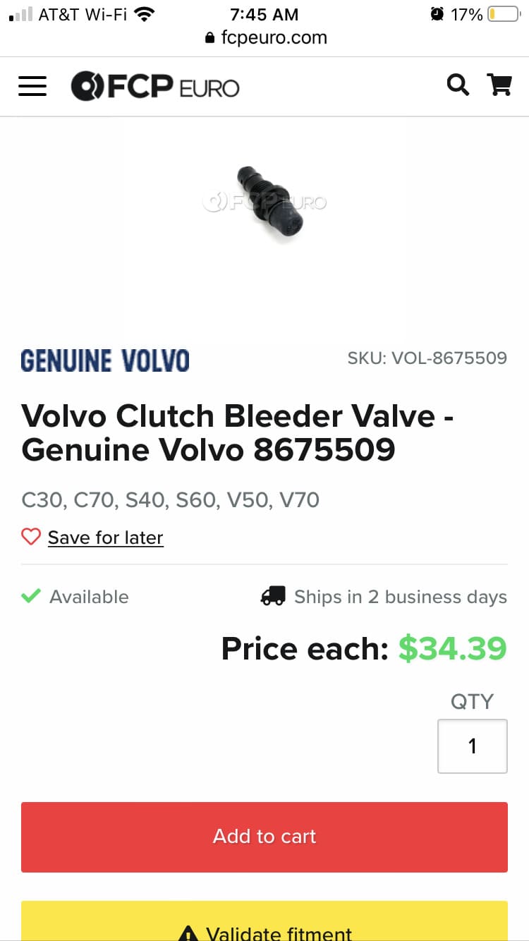
Sunday: Tracked down the part numbers for the hoses and couplers for the hydraulic hose. This way I could call Volvo in the morning when they open up. I did find that the coupler was sold alone and pops on the end of the hose. The coupler was $35, while the whole hose assembly was $200+. So since the coupler snaps over a metal hose, we are going to opt for the coupler alone.
Monday: Figured we would see if we could source a coupler close to home. Went to local parts store and no such luck. Called Volvo and the hose and couplers are special order and days away.
Then I remembered Volvo shares this same chassis and clutch pedal and other items with Ford Focus ST and Mazdaspeed 3. Hoping to grab the part locally I tracked down the clutch hoses for each of those cars. The images showed the coupler was identical. I called those dealers asking if the coupler was sold alone. No luck, they only sold the entire hose assembly.
At this point, called Volvo and ordered the coupler and some extra clips for the hose connect as mentioned above. Delivery would be at the dealer Thursday… so for now we just wait to try another day of bleeding.
If you are going to use the same hose, be sure to order new couplers and locking rings (part number link above), and save yourself this week long ordeal.
Entire clutch line: 31256074
QUICK COUPLING: 9181729
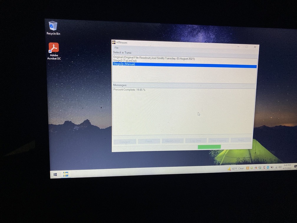
Day 13 – Tuesday: Flash & Tune
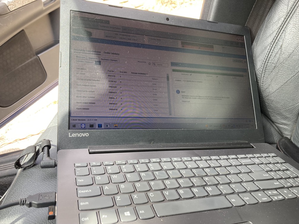
The appointment was already scheduled, and we knew the car fired up and ran, and we could not do any more bleeding, so at 2pm pst, we linked up with Hilton tuning for our CEM flash. Our ECM tune/flash was already loaded into the software so we flashed that prior to the CEM flash. Standard tune procedure. Took about 5 minutes, and car fired up after.
From there we let Hilton Tuning do their thing, which took less than an hour via remote access.
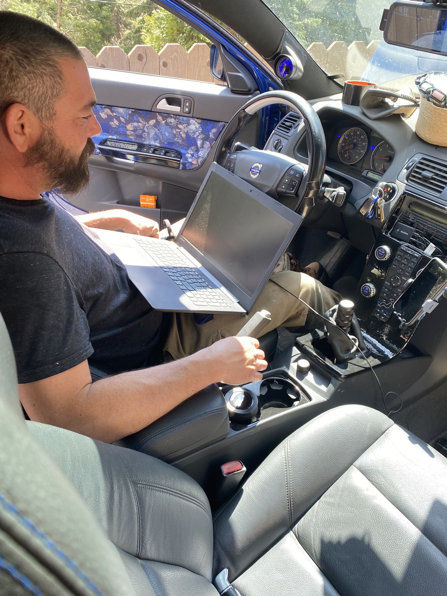
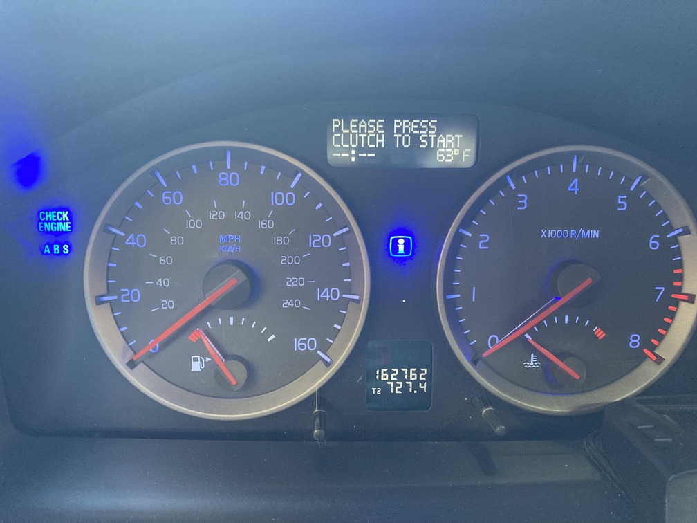
After that, the car fired up and we noticed two things immediately in the gauge cluster. The “-” mark, where the drive gear indicator usually was (P,R,N,D and 1-5 for geatronic) was gone, and now starting the car would give you the error message to “Please Press Clutch To Start”, if the clutch pedal was not down. So while the car started before, this was great and proved the entire car software was good to go. Also meant that lone harness for the clutch a few days back, was good to go and no special wiring was needed for the clutch position sensor on the master clutch cylinder.
Day 14 – Wednesday: Wiring
Since our clutch line parts are still a day out we decided to attack the wiring. Especially since now the ECM and CEM were flashed, we could start the task of the two items, that anyone with the M66 swap on a P1 have not completed. So now we get to further claim this is the “FIRST COMPLETED” m66 on a P1 and only documented on an S40.
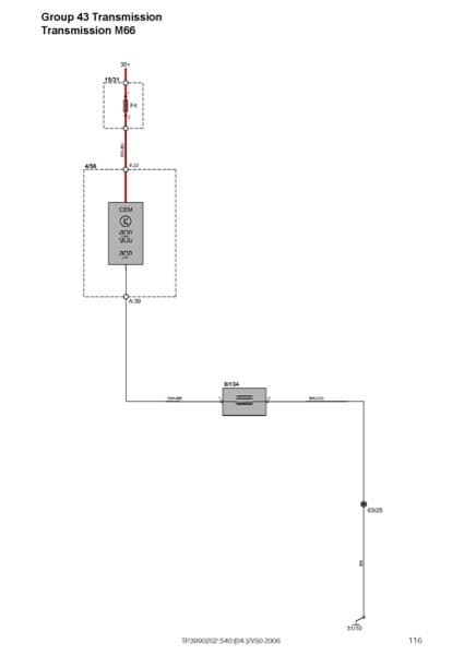
Reverse lights and reverse lockout wiring are at hand. Last week we spent hours going through the P1 wiring diagram for the car. Hundreds of pages and learning a new wiring language. Here was the resource we started with: Volvo S40 Wiring Diagram.
The reverse lights had all the diagrams in the book. We pulled and printed the top related pages and studied them closely. Took hours to decipher, and then longer to track down the connections in the car and follow wires. Here are our personal wiring notes we worked with in pdf form if you want to geek out, but if not we’ll explain how to do it in 10 minutes below.
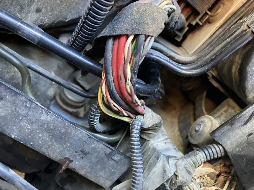
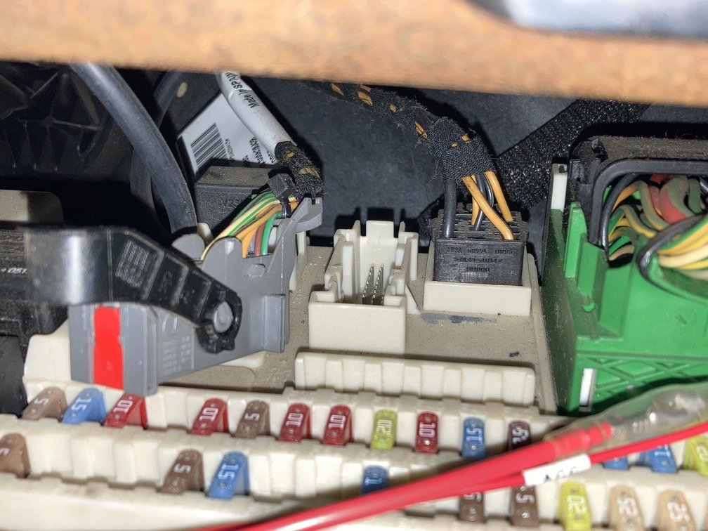
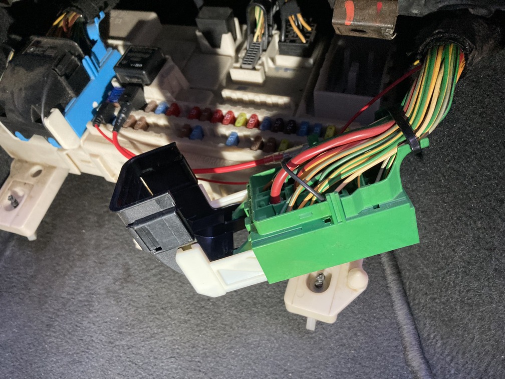
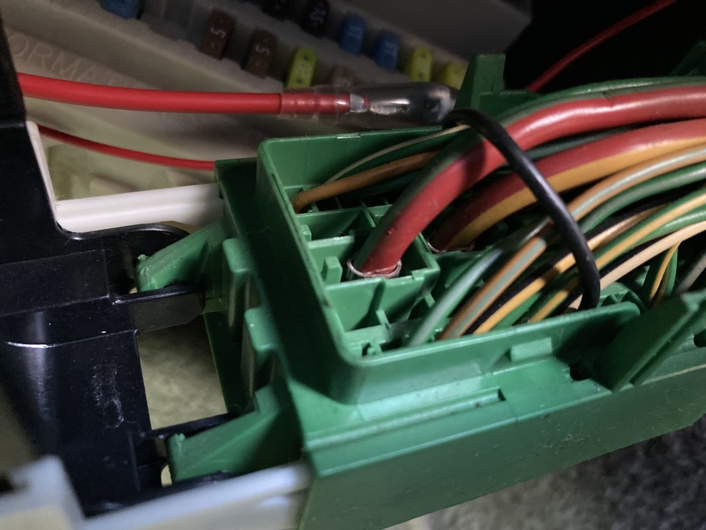
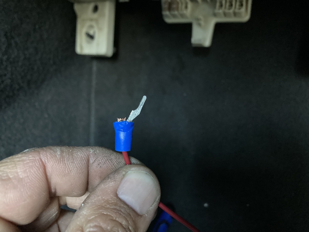
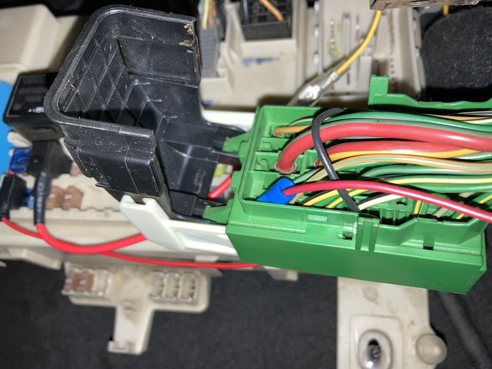
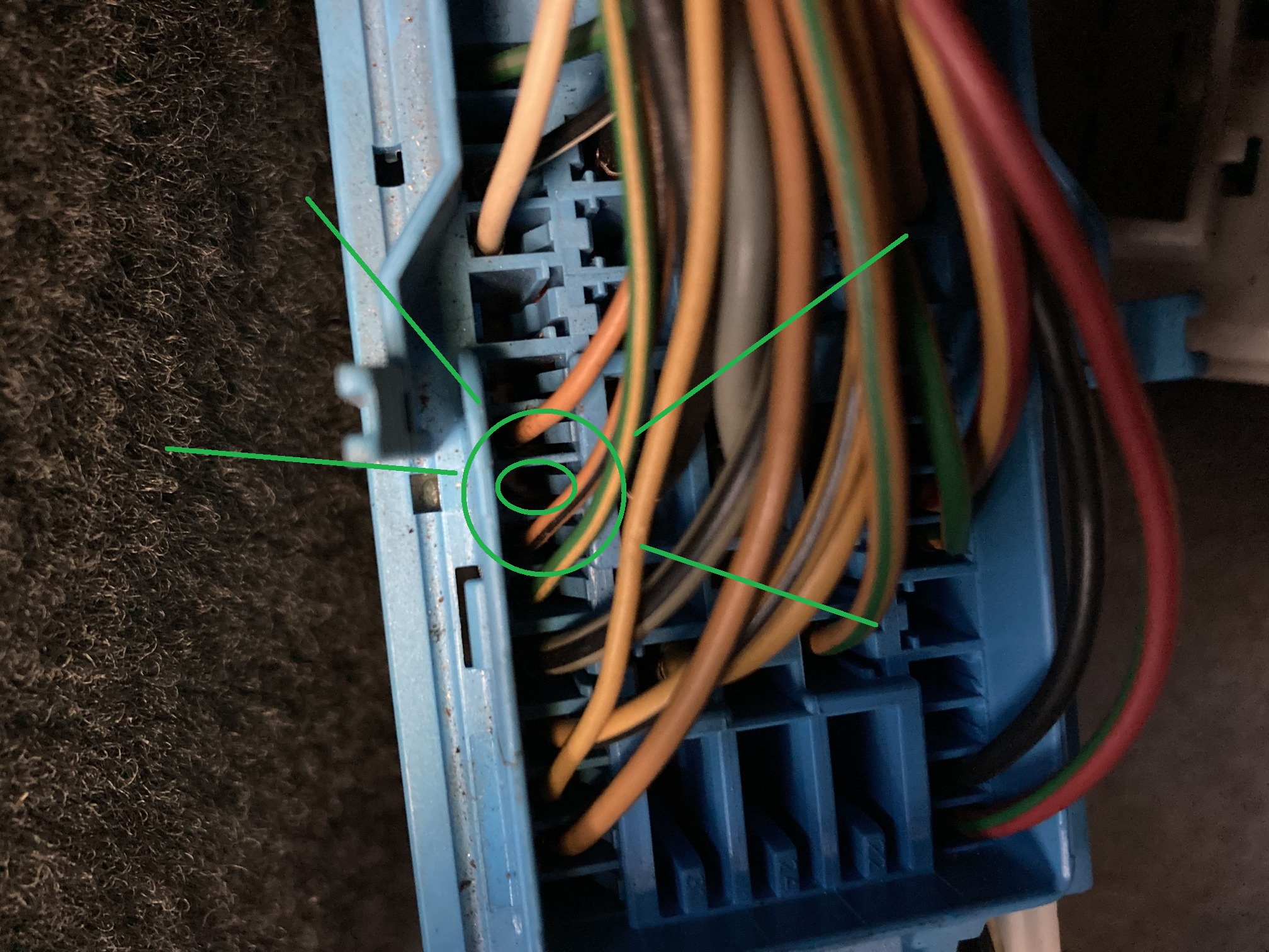
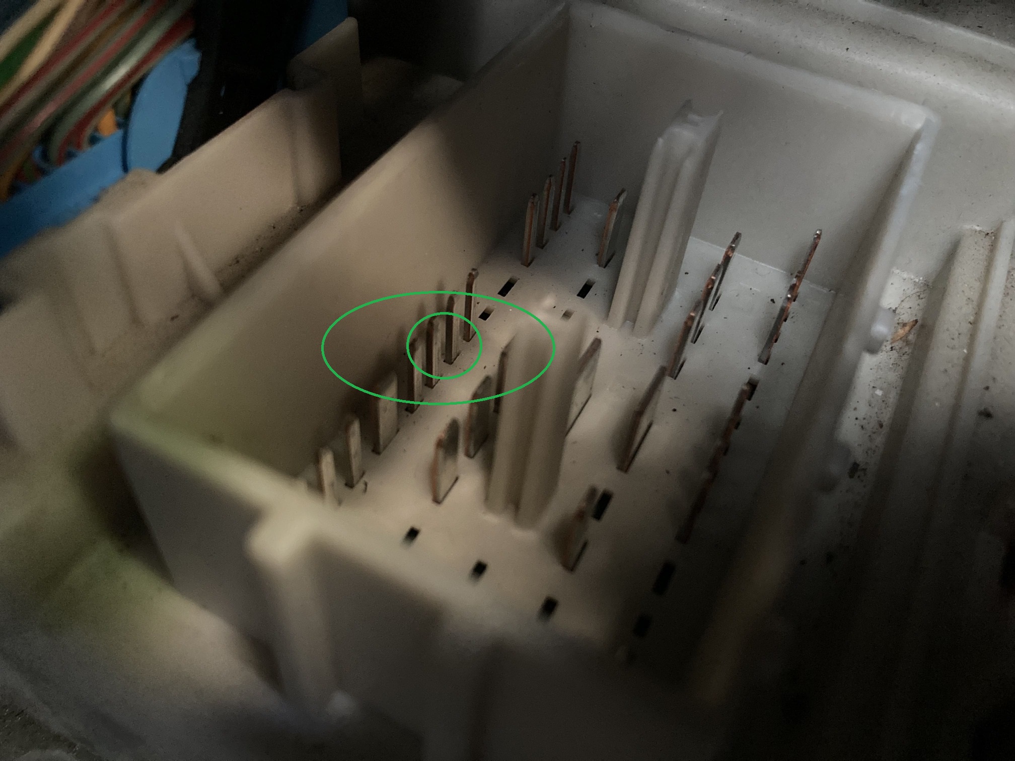
Essentially you have two wires from the reverse sensor on the trans. A black for ground and a Green/Yellow wire to hit the CEM (fusebox). The black wire from the factory goes into a harness and routes up to the grounds on the strut tower on the driver side behind the battery, with the other handful of grounds… easy. The Green/Yellow goes into a harness, meets a connector and then changes to Green/Blue, which then hits the CEM at plug E:14. E:14 is labeled and it is easy to find. Open the fuse box and pull it out as far as you can. On the right of the box is a large green harness. Pull that off and E:14 will be the very top left wire, the only Green/Blue one you see.
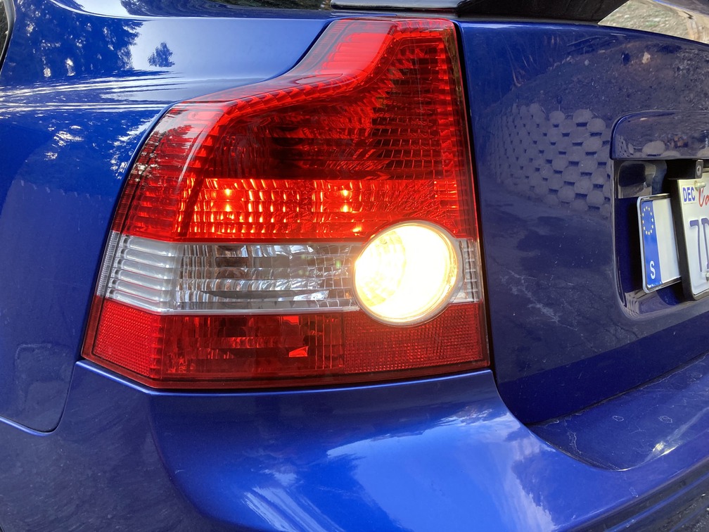
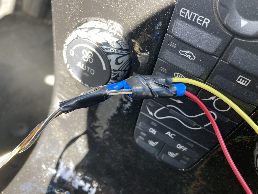
For execution, simply splice a wire to black, and run it up to the strut tower and bolt it down to ground the switch. The Green/Yellow you will splice a wire in, run it along the firewall, then through the firewall into the cabin on the passenger side with the factory wire harness. It will pop out behind the glove box and from there you are able to tap it to the fuse box harness. There are no markings on those wires, and 5 harness to use. We pulled out each one looking for the Green/Blue and only found one. After pushing the wire in, and putting car in reverse, our lights illuminated. So from here we spliced the end of the wire with a cut down u-connector and simply pushed in down into the pin. Sure we could have cut and spliced and all that for a cleaner finish, but there was little room and we didn’t want to cut the original harness in any way.
After doing the reverse lockout wiring explained below, we did get some resources from Facusan on Swedespeed, which would have made this easier, which was the vida wiring breakdown of the CEM, get a copy here. This shows exactly what pin and how to identify them.
Day 14,15,16,17 – Thursday-Sunday: More Wiring, more bleeding…
While the car was drivable I was experiencing some gooshy clutch pedal and then some stiff pedal, so I did a few more bleeds in these days, and think I still have one more yet to do. I wasn’t bleeding all day everyday, just driving and pumping and feeling pedal over this time frame.
More wiring headaches: So during this time I was attempting to get the reverse lockout dialed in, trying a few wiring configurations a day and test driving and such. The wiring diagram seemed easy enough, but without much help I was fumbling around. Here are the two diagrams I was using.
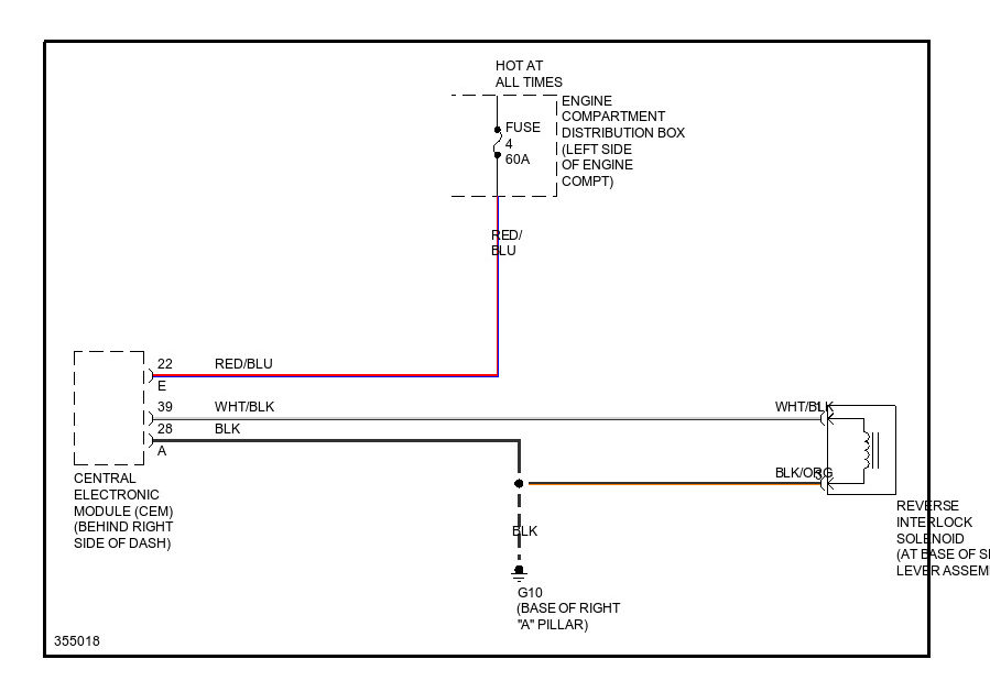
Easy enough as it looked. We spliced into the lockout solenoid and ran our wires out under the center console and over under the glove box. Ain’t pretty, but it works.
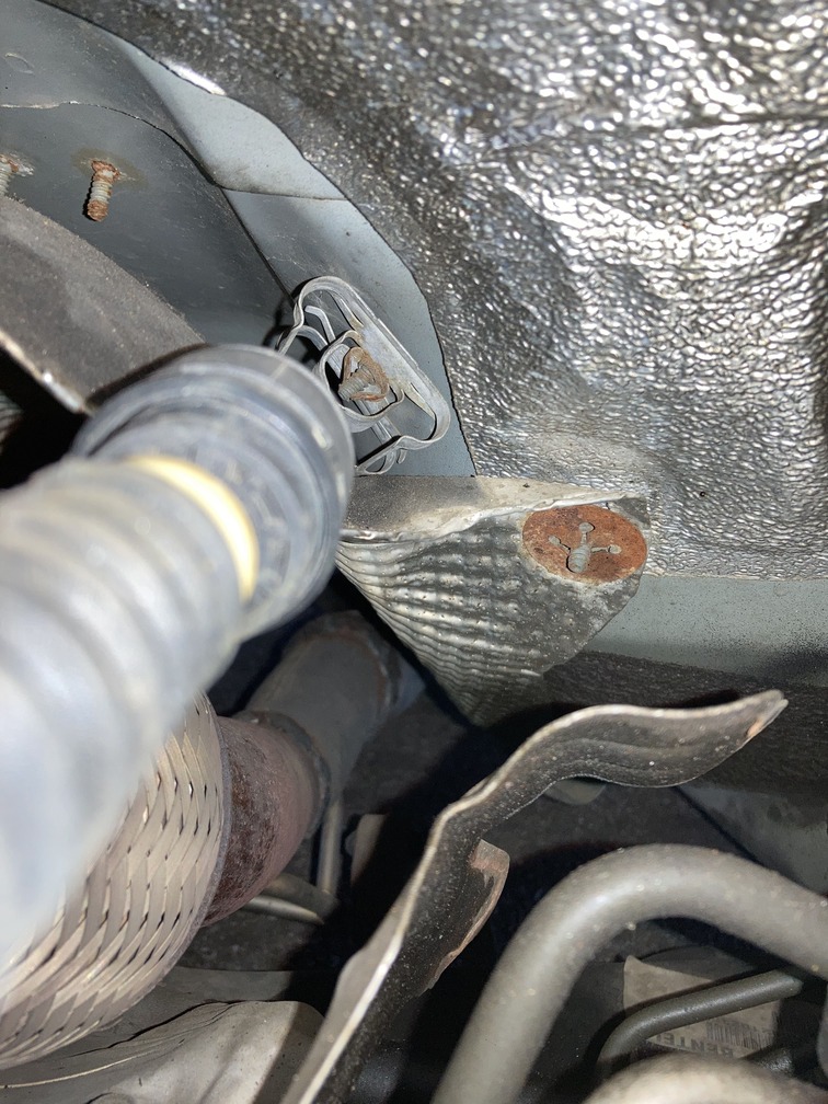
From there, orange/black wire is grounded on the chassis on the passenger side of the car. Here is where we did, and then also where the factory would have had it run, either way works.
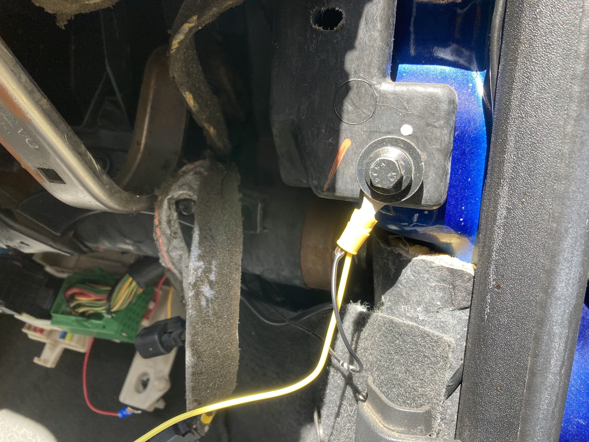
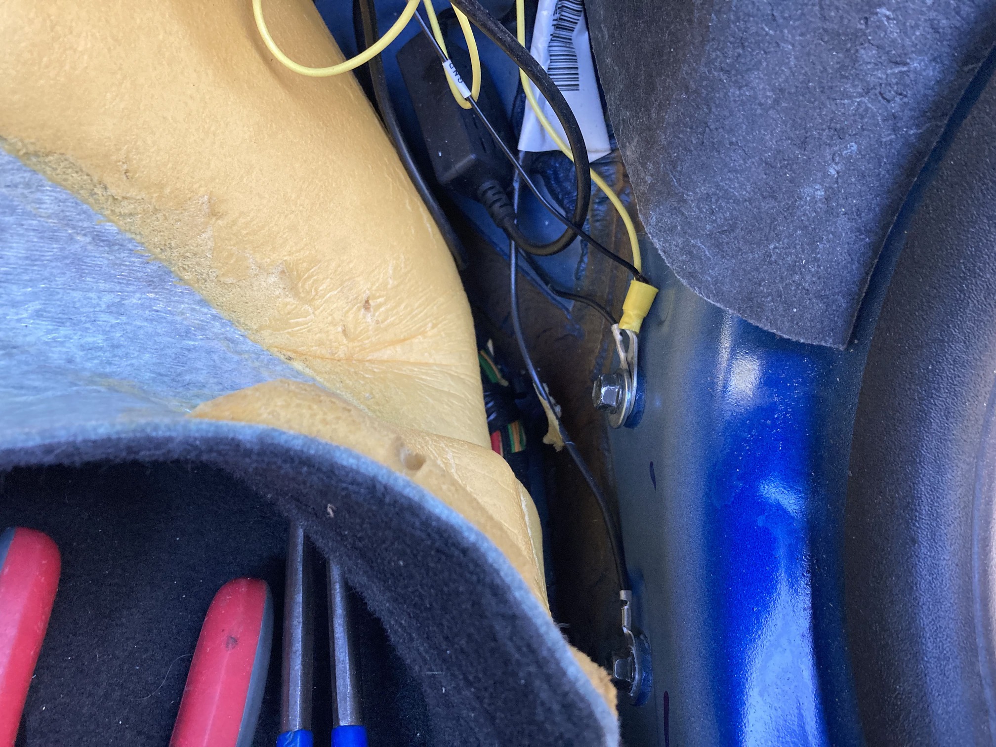
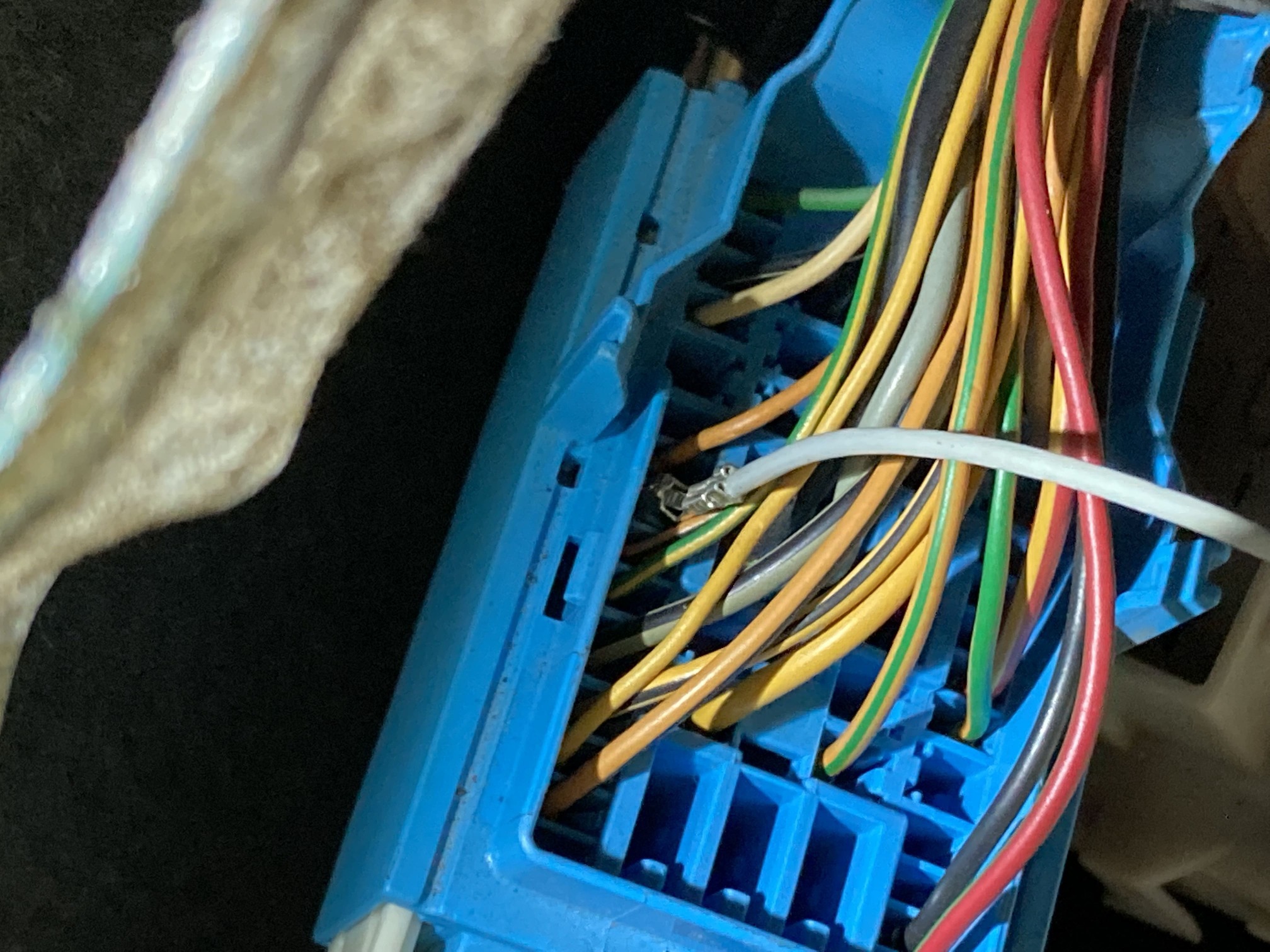
Next, the white/black wire goes into harness A:39. This is the blue harness on the left of the CEM, and then wire pinned into 39. This was made easier again, with the help of this vida guide.
When you look close on the bottom, you will see the pin holes numbered, and also here is the volvo diagram.
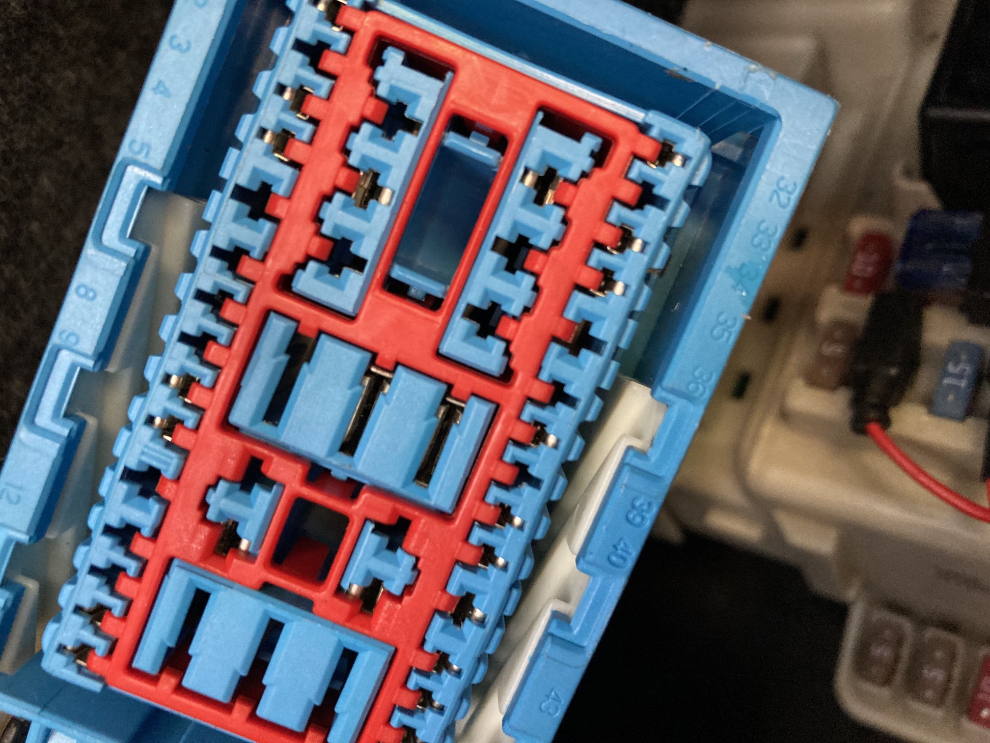
Starting at 32, count over to 39 and you will see it is an empty slot on the harness.
If you look at the CEM, and count over you will see there is a pin for 39 to send the signal, but just no wire present on our AUTO harness.
From here we opened some backup harness connectors we keep around for spare pins, and fashioned up a pin on the end of the white/black wire…which is now red after splicing from the shifter.
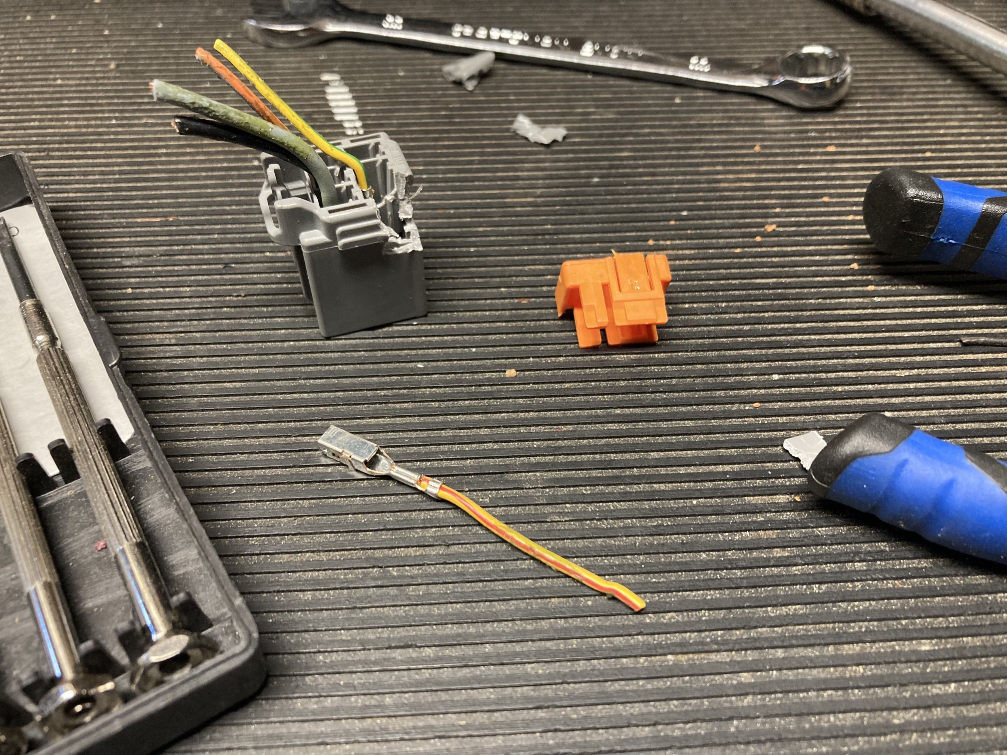
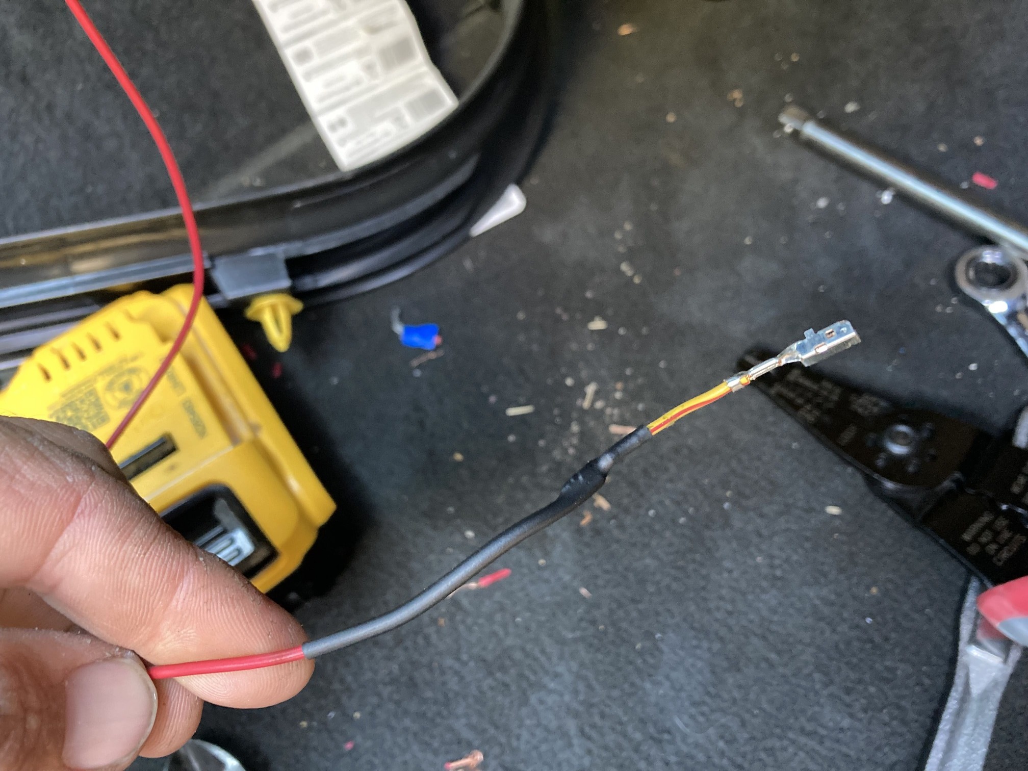
Next, pop and slide that all the way down in the harness to make sure it will meet with the CEM pin when plugged in.
From there you are done… or should be. It took us a few days trouble shooting to get to this point. We don’t have vida and went in blind so initially I was plugging onto the wrong harness, then swapping wires, then trying all kinds of stuff. Some help from Facusan on Swedespeed really got us in the right direction. Could not figure it out, until he asked if we had check engine or dash messages. We did, ABS and something else. He mentioned the CEM may not function properly with these codes and recommended we clear them.
Without Vida I just decided to use my Hilton tuning software and re-flash the entire car with my tune files, since this always resets and clears codes. Did this once, more codes present and lost all power steering function and then re-flashed again and all codes gone and went to drive.
BINGO!!! Interlock was activating at 15.53mph, 25kph.
more coming daily….
This swap documentation is still in process… uploading images and content.
…
Test Drive Reactions
…
The Numbers – HP & TQ Stock AW, Tuned AW, Stock M66
The Day before we completed the swap, we ran a few pulls around town to see what the peak hp and tq were. This is under the assumption (based on internet claims) that auto trannies vs manual trannies can see up to 10+% hp loss to the wheels based on more moving parts, and thus power delivery loss. If this is true, then simply swapping to the M66 should give us some HP gains as well.
We have logged well in the 300+ HP range after our last round of bolt-ons, but for this test we were on a tranny that was failing, so searching out a drag strip was not in the cards. We did a 10 minute canyon drive, but hit traffic and were not able to get out out 2nd gear much, and even in third were not able to get past 4500 rpm. So this sampling is not for maximum hp output, but rather we will do the same run after the swap and compare numbers based on the driving traffic condition limitations.
Pre Swap:
Engine RPM: 4900
Vehicle Speed Sensor: 48
Calculated engine power: 246
Calculated engine torque: 264
Post Swap:
Engine RPM: 4623
Vehicle Speed Sensor: 66
Calculated engine power: 296
Calculated engine torque: 336
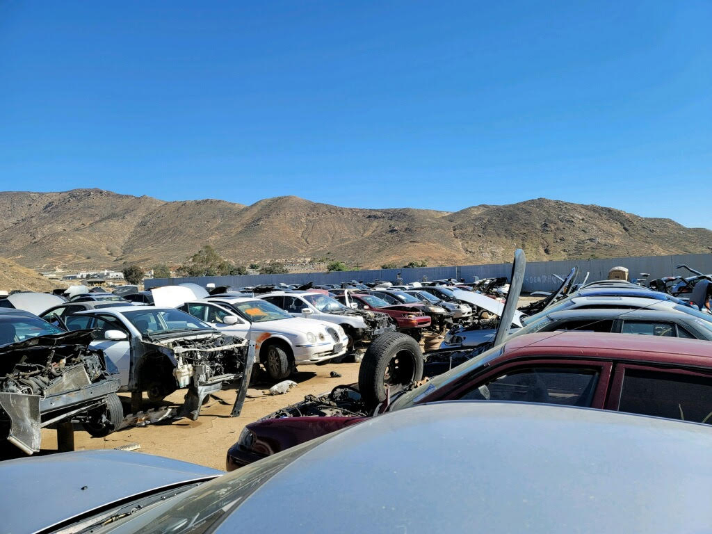
Junkyard Time


