


Aggressive Styling & Handling, for Less than $300 and 3 Hours
Lowering springs are one of the cheapest and easiest mods to do, and they ALWAYS provide instant gratification. For the average DIYer, all the way to advanced car modifiers, stance is typically on the mod “to-do” list. Aside from making almost any car look better, handling is often improved as well. Best of all, you can purchase quality, brand name lowering springs for almost any vehicle, for between $200-$400. Installs can be completed at home with the tools you already have, and before sunset, you’re cruising and looking good. Maybe its a placebo, but most also report that they feel about 10-15 HP from the install… probably placebo.
So as manufacturers continue to pump out new models in their line-up, so do aftermarket parts companies. Lowering springs are no different. Here, we wanted to provide a detailed step by step walk though of a lowering spring install on a popular Japanese rig, the Suburu WRX Sti. We were pleasantly surprised at how easy this spring swap out was, and if you follow along, you should be able to complete your install without a hitch.
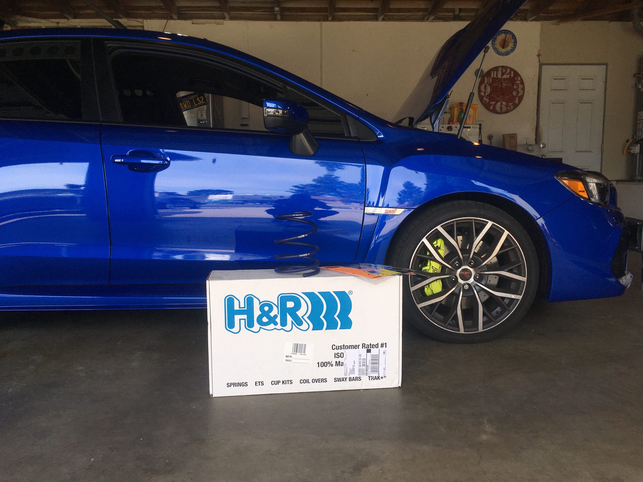
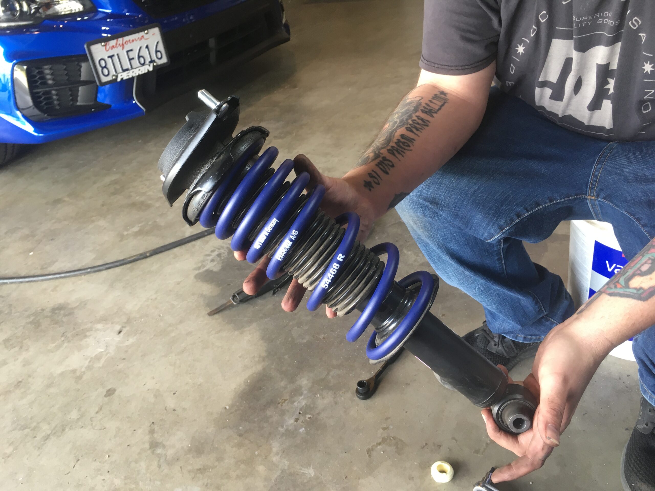
With a handful of options avaiable for this car, we did some forum research to see what people were, using, what they liked, and decided to go with H&R lowering springs. The price was perfect at about $260 including shipping. We had also installed a set of H&R springs on our 01 Prelude a few years back, and we remember how great they were. The drop on these springs is decent at about over an inch all the way around, shipping was free, and delivery was 3 days flat from MAPerformance.com. You can see the item in more detail on their website here.
Experience level: General automotive knowledge and familiarity with mechanic hand tools.
Time to completion: 3-4 hours.

Tools Needed:
12mm, 13mm, 17mm and 19mm Sockets
3/8 and 1/2 drive ratchet and extension
13mm and 17mm ratcheting wrenches (a separate socket and drive will also work)
Jack and jack stands
Needle nose plyers
Rubber hammer
5mm and 6mm allen wrenches or allen sockets
Pass Thru ratchet and socket set (17mm and 14mm used for this installation) – we featured this tool here
Interior panel removal tools (or flathead screwdriver)
Optional:
Air gun
Magnetic bolt bowl
A buddy to assist (we probably cut the install time in half with 4 available hands)
Torque Specs
Front Struts & Related:
Top hat connection to strut tower 15 ft-lb
2 strut lower bolts to knuckle 114 ft-lb
Brake line bracket on strut assembly 23 ft-lb
Strut/shock center bolt (nut and allen) 41 ft-lb
Rear Struts & Related:
Shock top hat to body (in trunk) 22 ft-lb
Lower shock assembly to the lower control arm 89 ft-lb
Lower control arm inner bolt to subframe 59 ft-lb
Tie rod end-link to control arm 33 ft-lb
Strut/shock center bolt (nut and allen) 18 ft-lb
Attacking the Front
We decided to do one side at a time, to reduce total parts laying around, and to make sure all our attention was focused. Here is how we went about it:
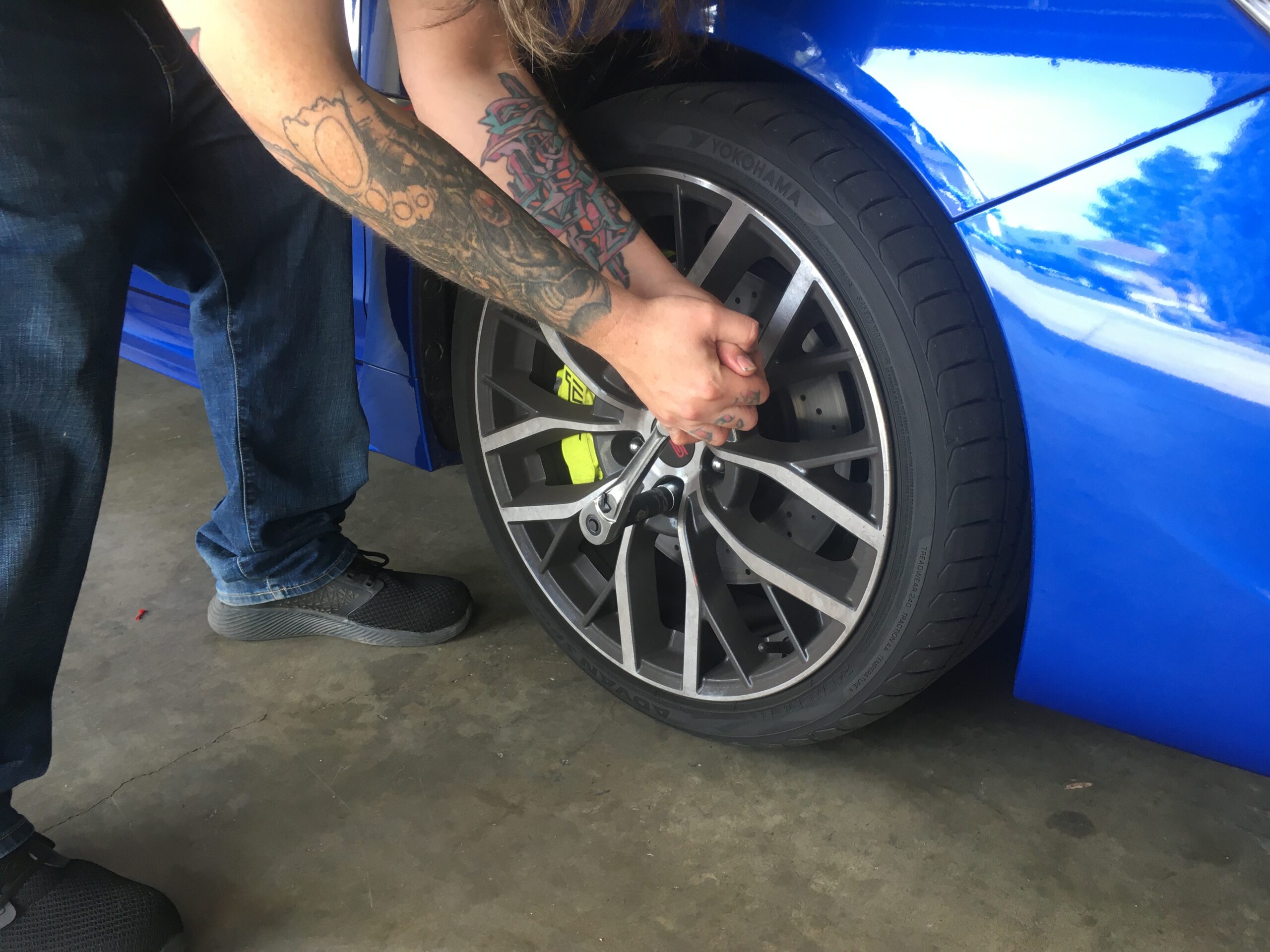
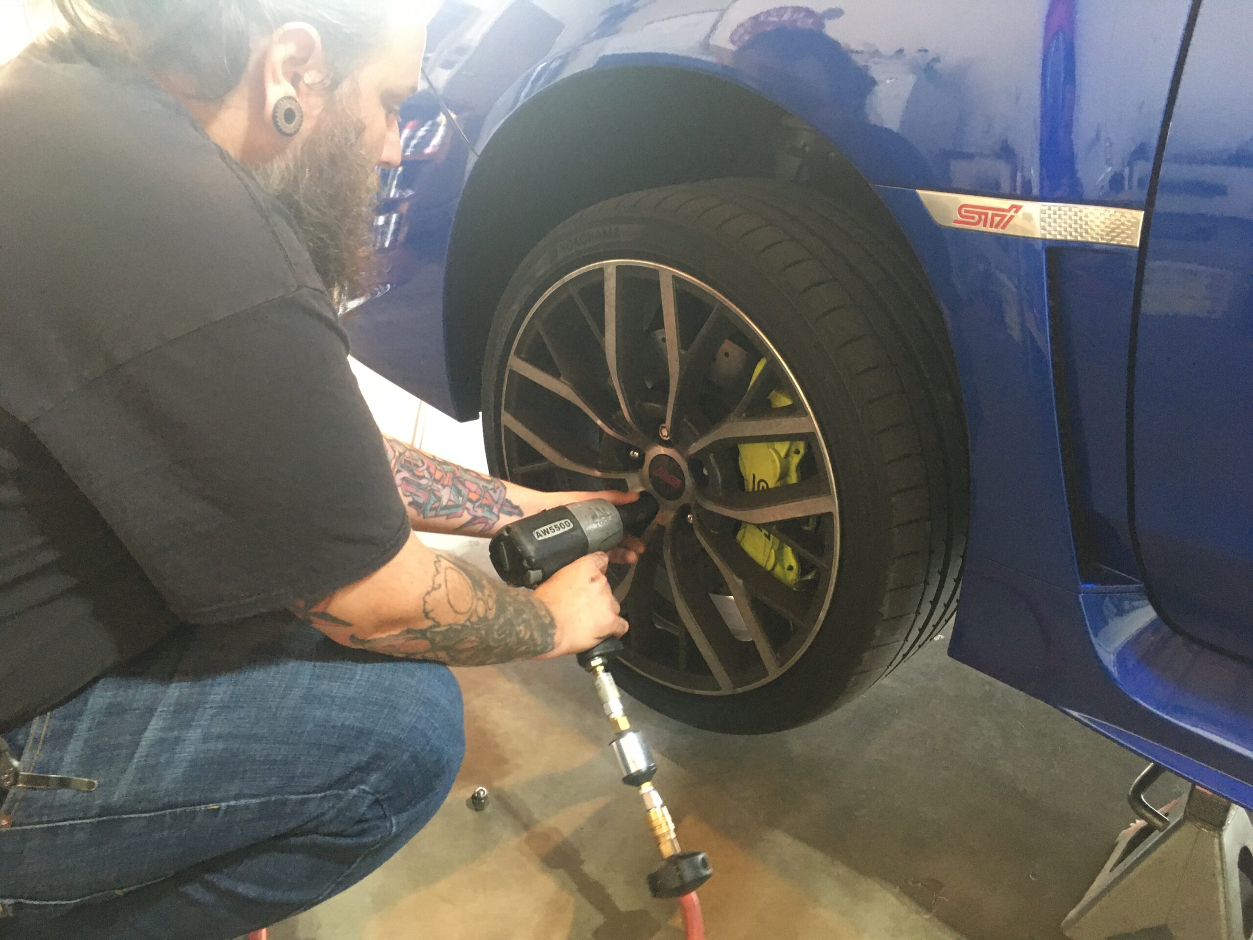
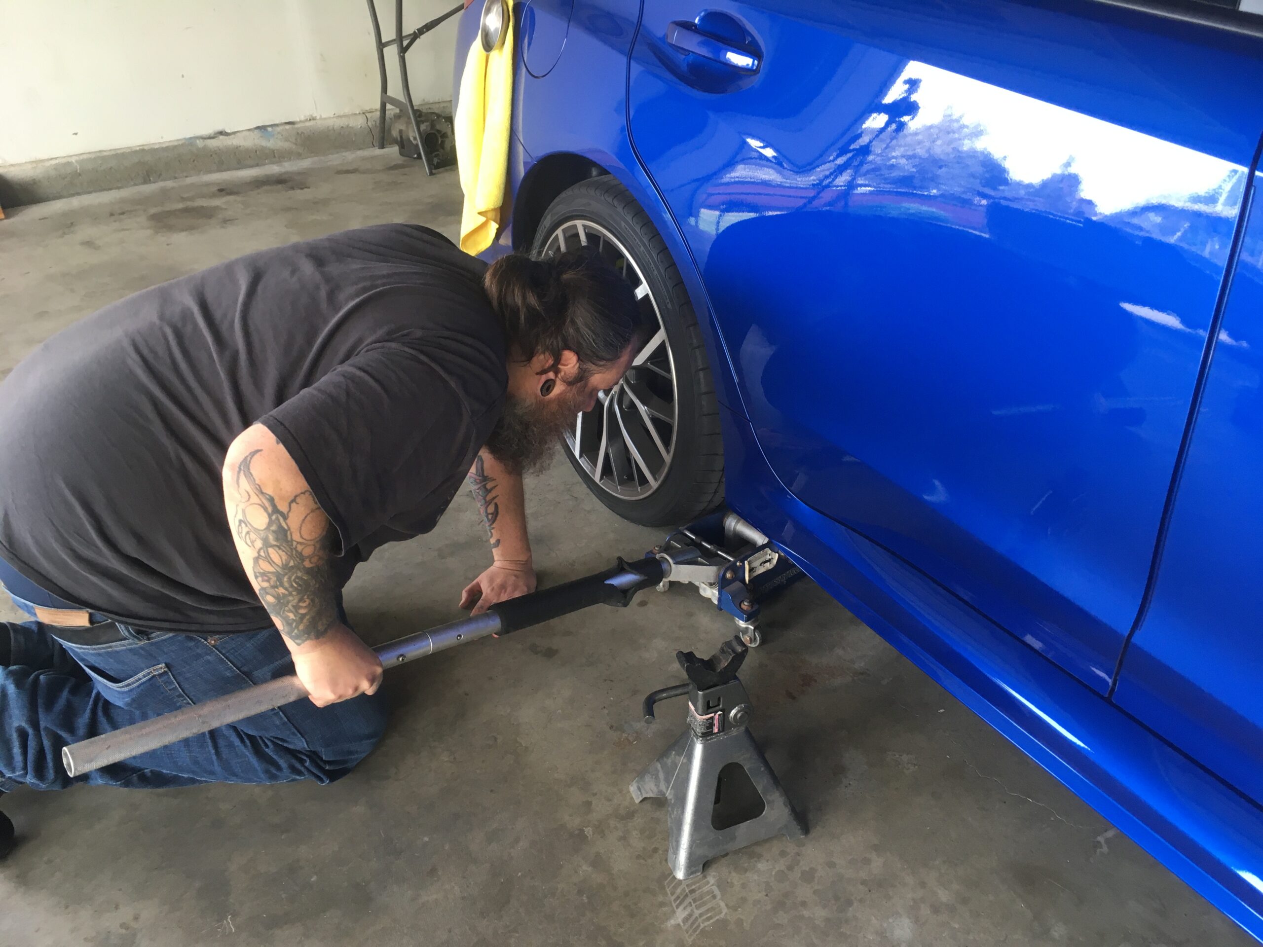
19mm, 1/2 drive ratchet and short extension. Break your lug nuts loose before putting the car up. We always find torqueing against the ground is better than against a tranny or diff. Extension is optional, but we like to keep the ratchet a few inches away from the body to avoid any ooops.
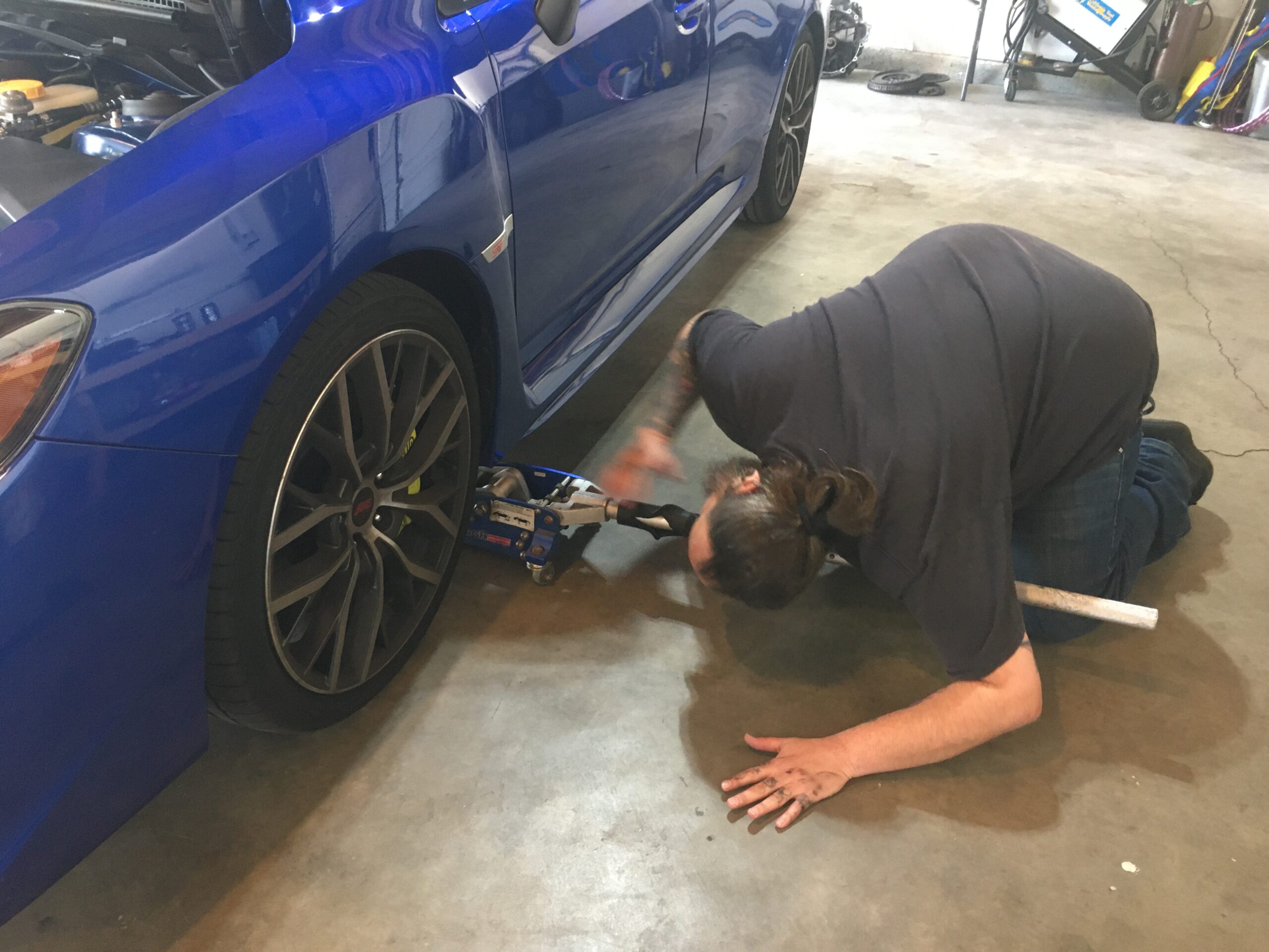
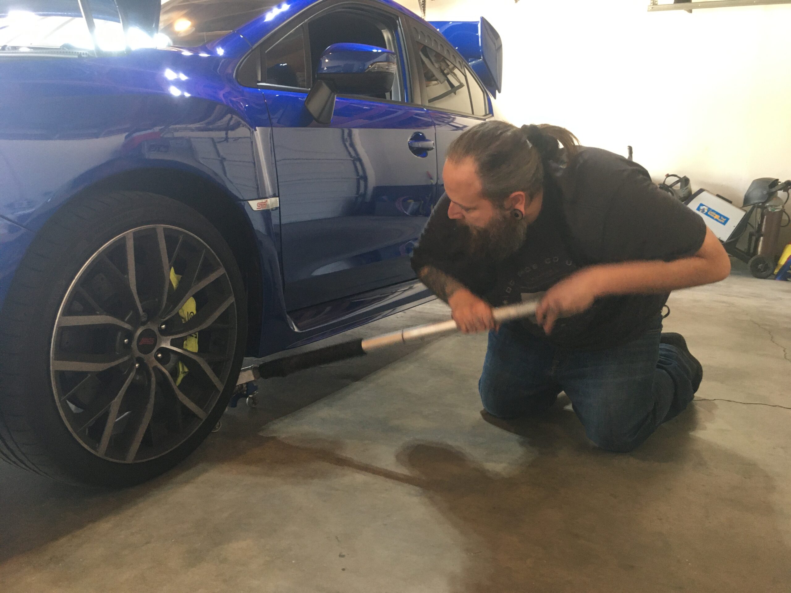
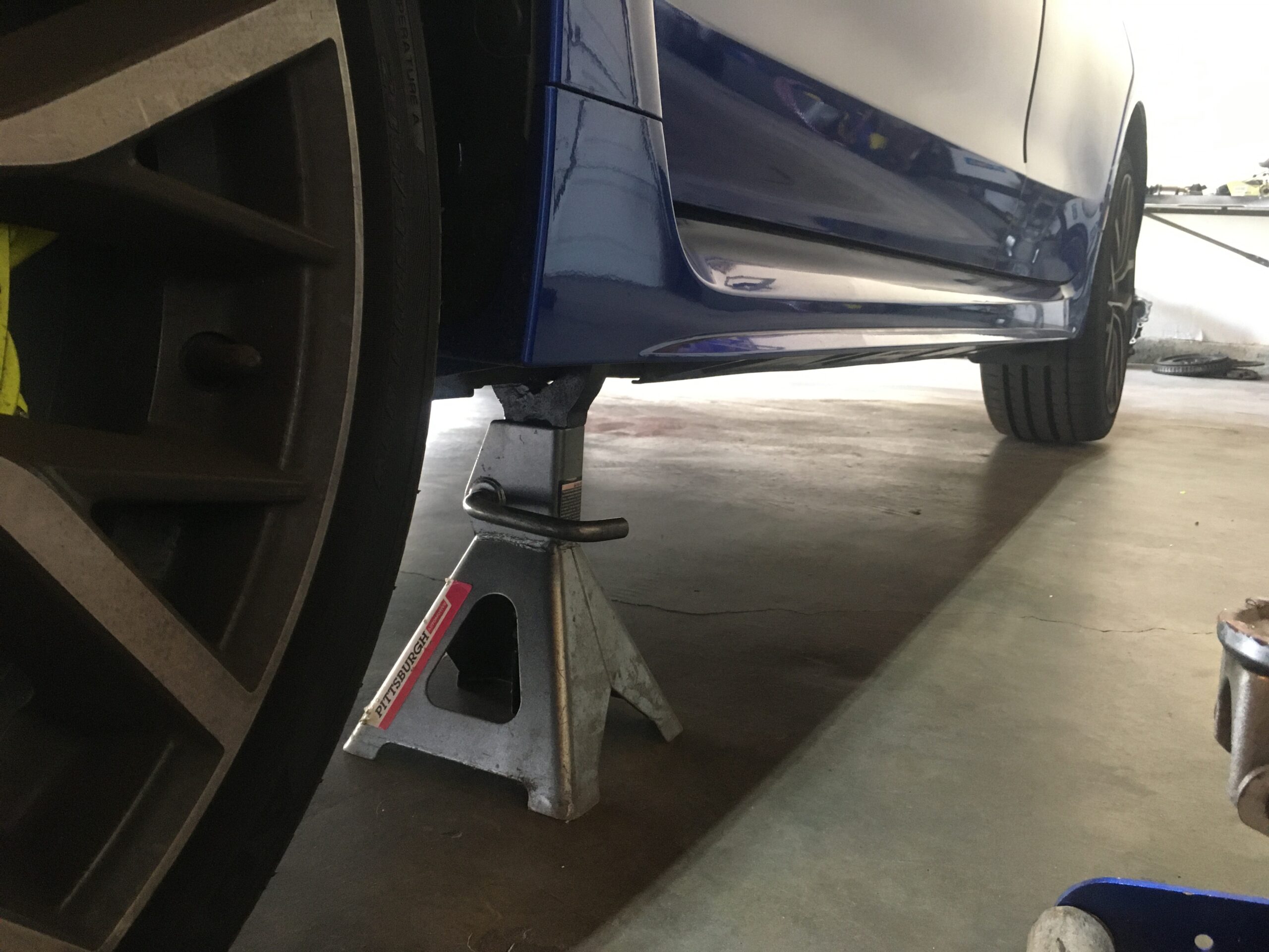
Jack stand and Jack. As mentioned, we did one side at a time, so we only lifted one side up. We placed the jack under the sub frame, put it a few inches past tire off the ground, and then slid the jack stand under the pinch weld. We lowered the car onto the stand, and then gave the car the standard “heave ho” to make sure we were solid. We’ve been using the affordable Pittsburg Automotive 3 ton aluminum stands for years and for about $50 we’ve gotten our monies worth. Like a fine wine, we pair our Harbor Freight tools together, here we used the Pittsburg Automotive 1.5 ton low profile rapid pump floor jack.
Remove lugs all the way and then remove the tire.
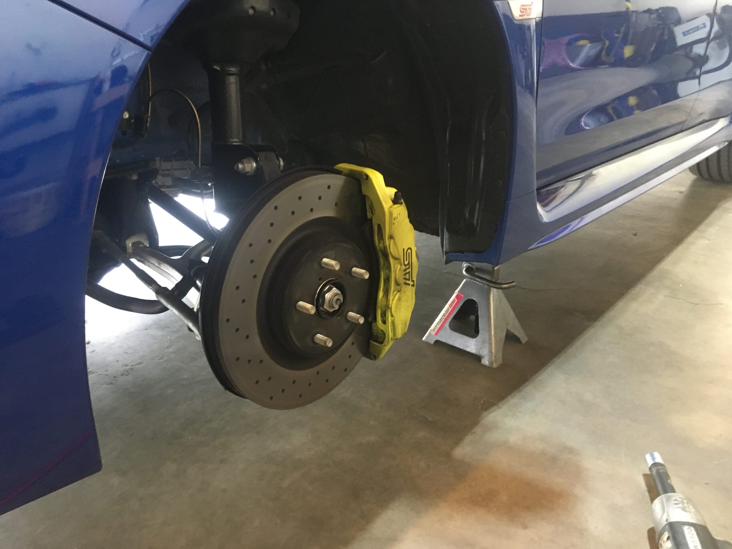
Inside the Wheel Well
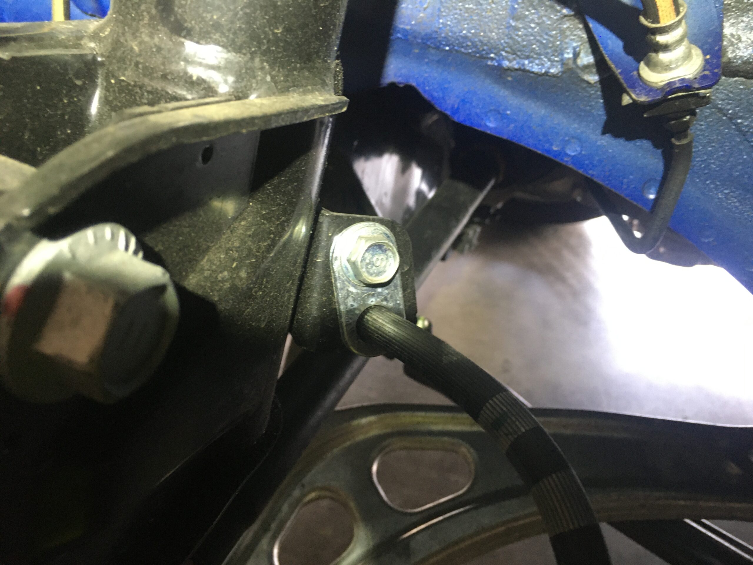
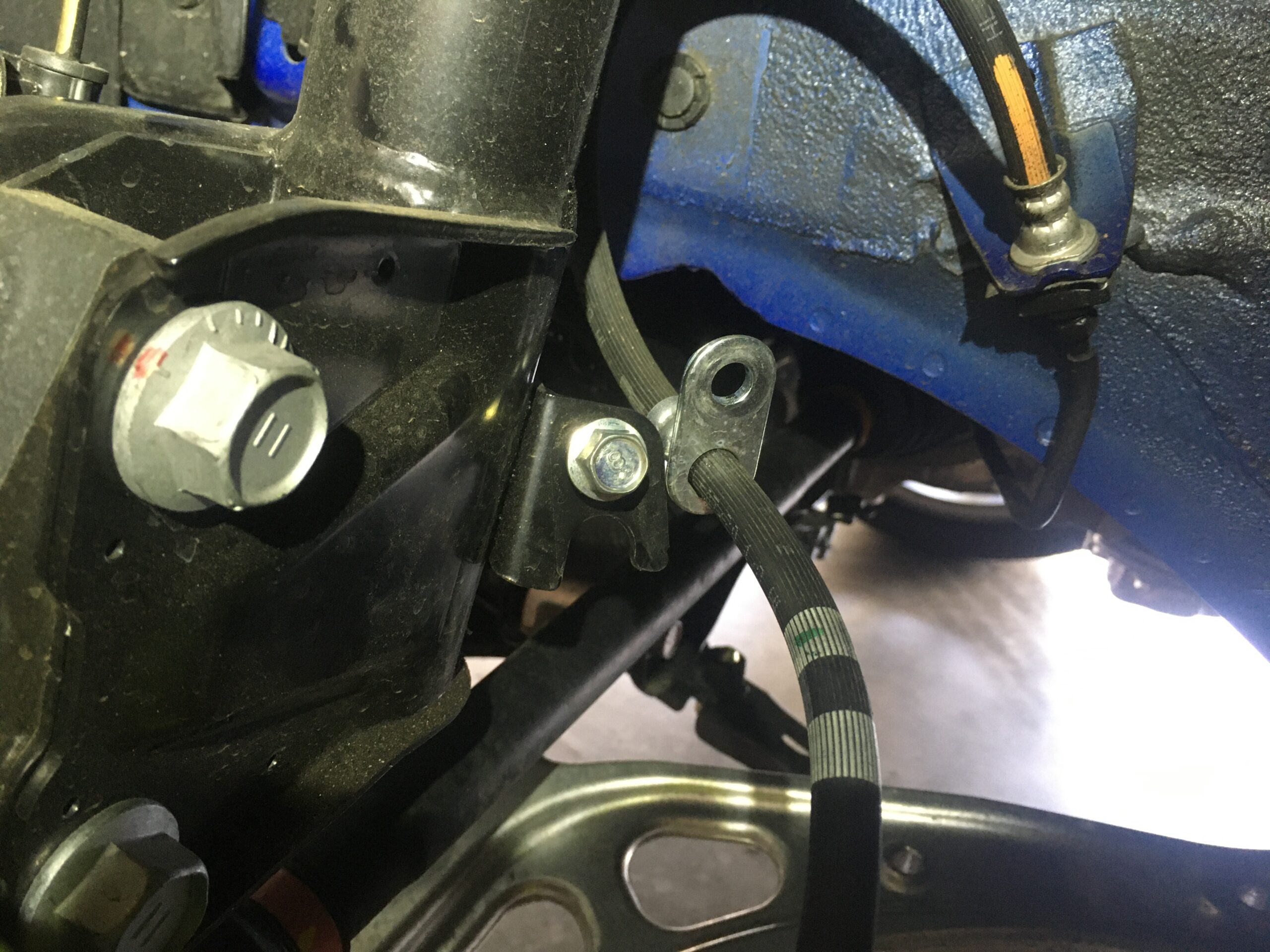
Here we need to remove a few lines (brake fluid line and ABS sensor line) which are attached to the strut assembly.
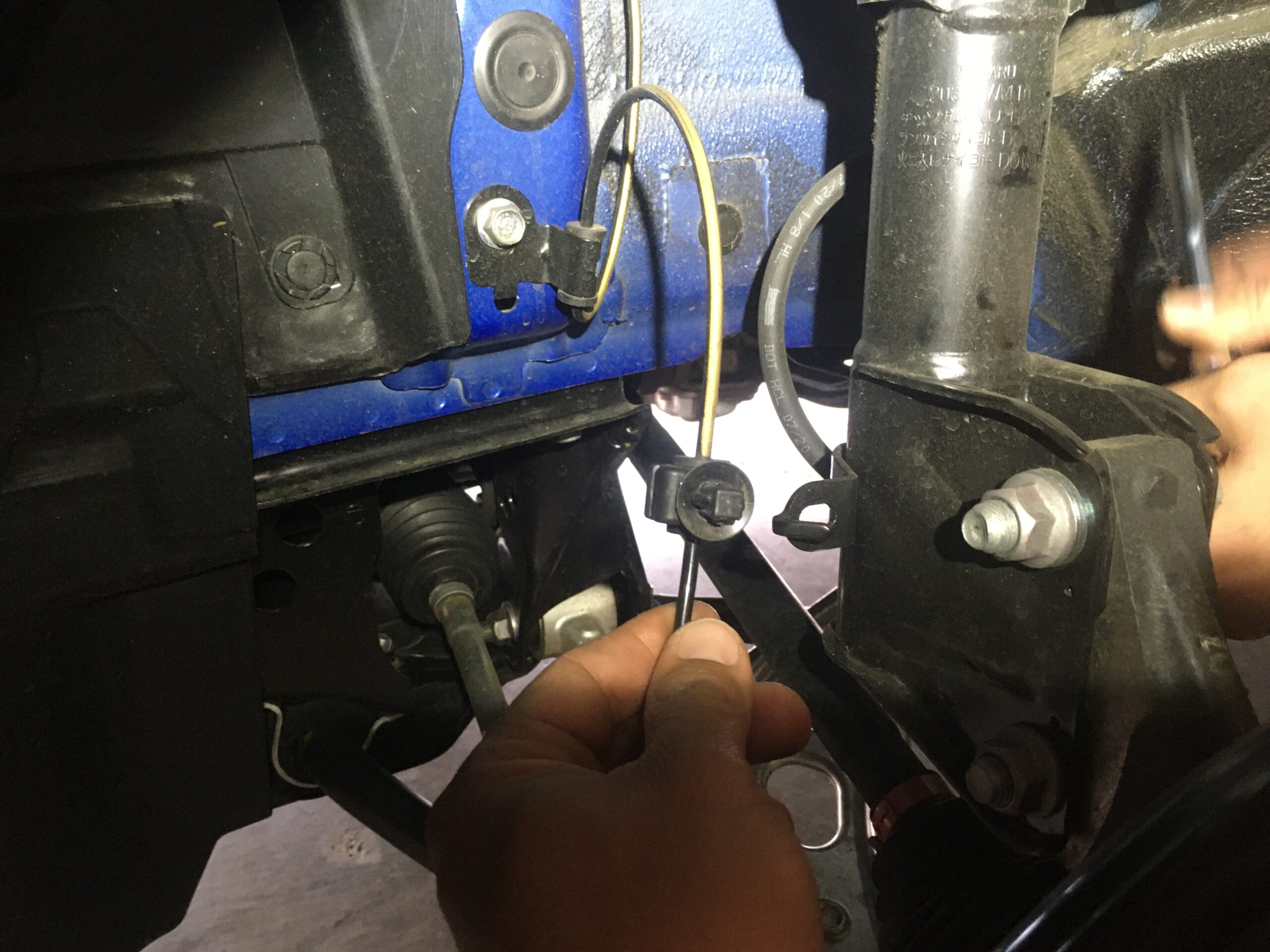
Needle nose plyers are used to remove the ABS sensor line that is connected to the strut assembly with a plastic tree style push clip. Pinch the clip and push it out backwards.
12mm socket and a 3/8 ratchet and extension are used to remove brake line. We put the bolt back for safe keeping.
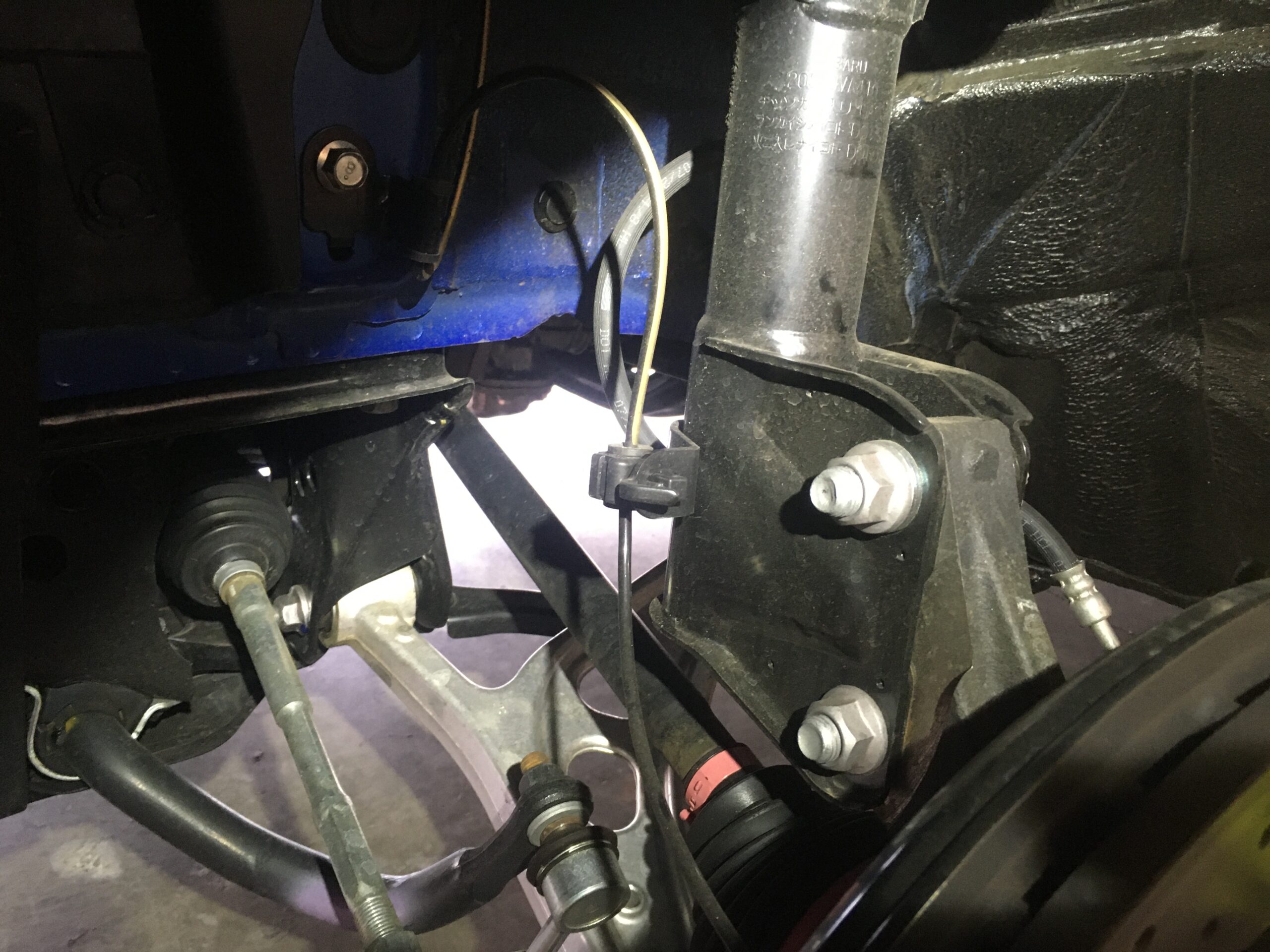
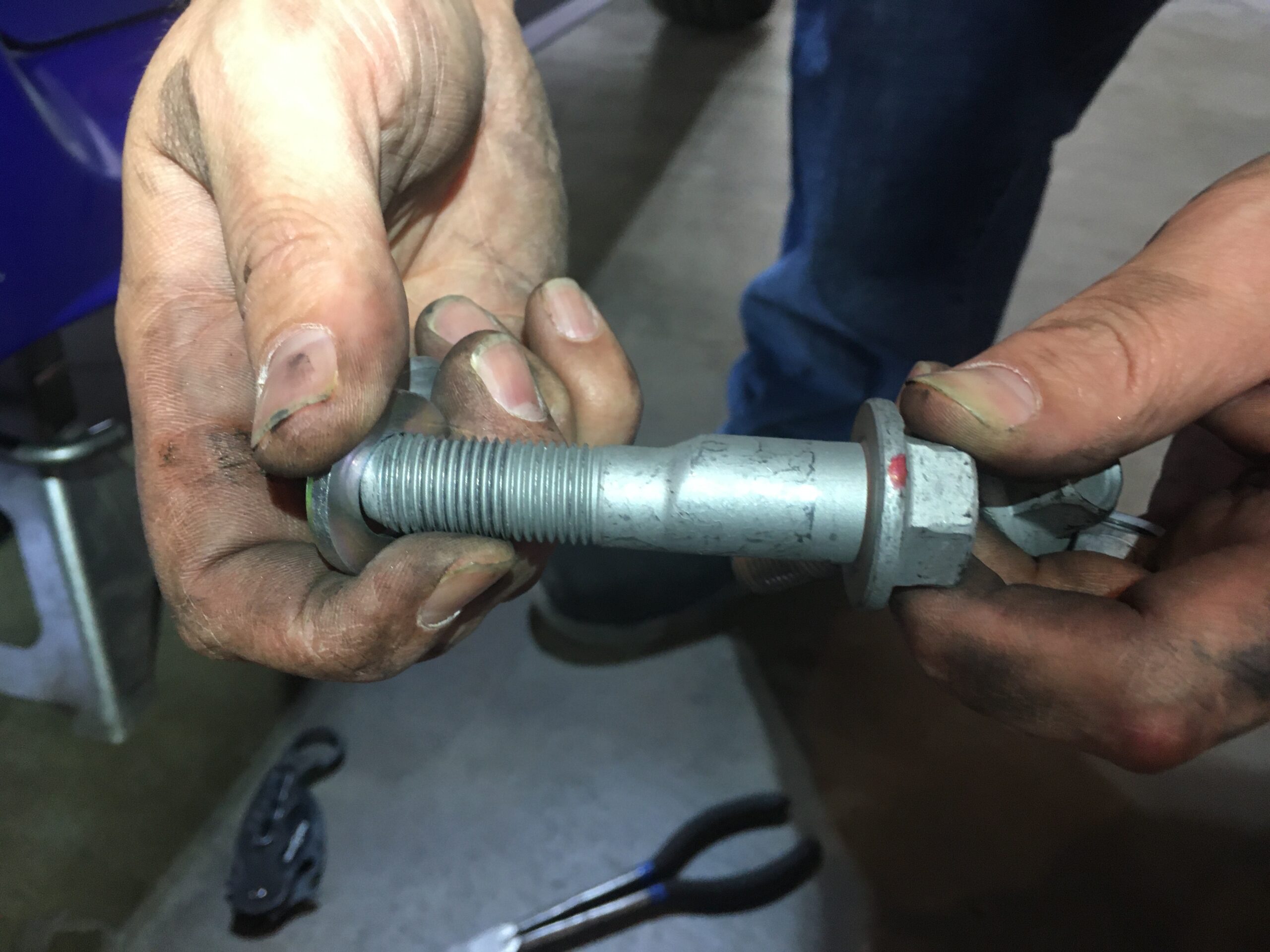
Red Sharpie Marker, a 1/2 drive 19mm socket paired with a MAC tools air gun were used on the lower strut mount bolts. There are 2 of these and the top bolt is hub-centric. The top bolt also utilizes a washer while the lower does not. You want to mark alignment on the top bolt prior to starting to make sure it goes back in with the same orientation. To pop the bolts out, we used a rubber hammer and our extension.
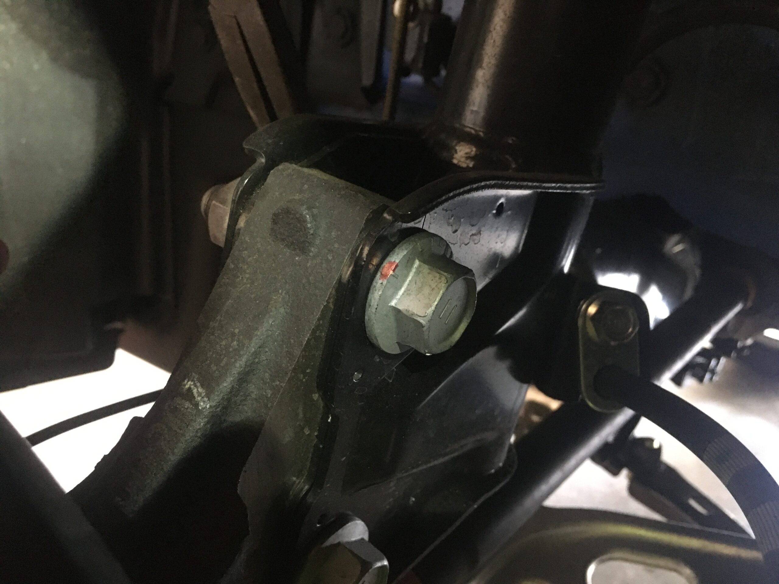
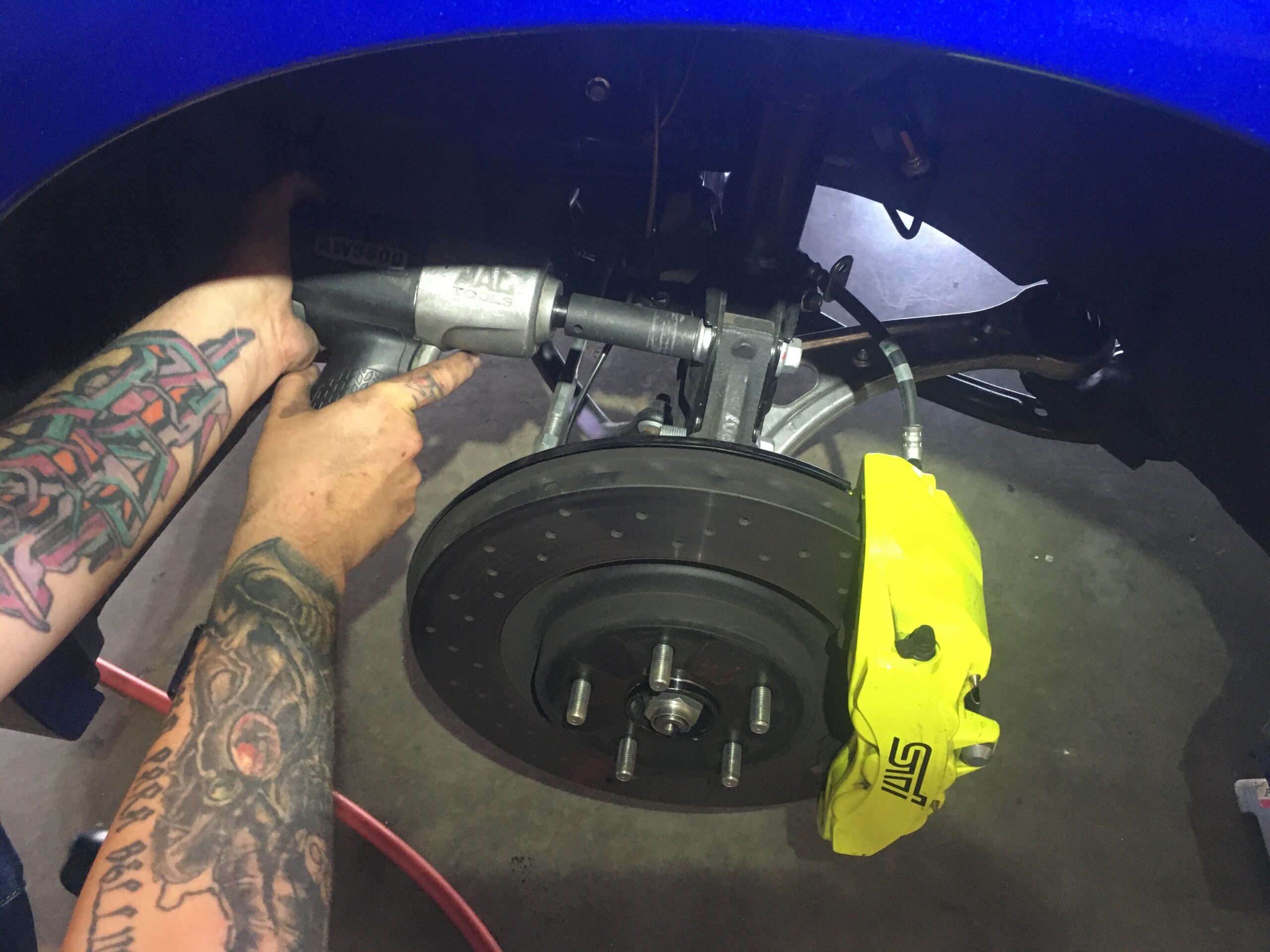
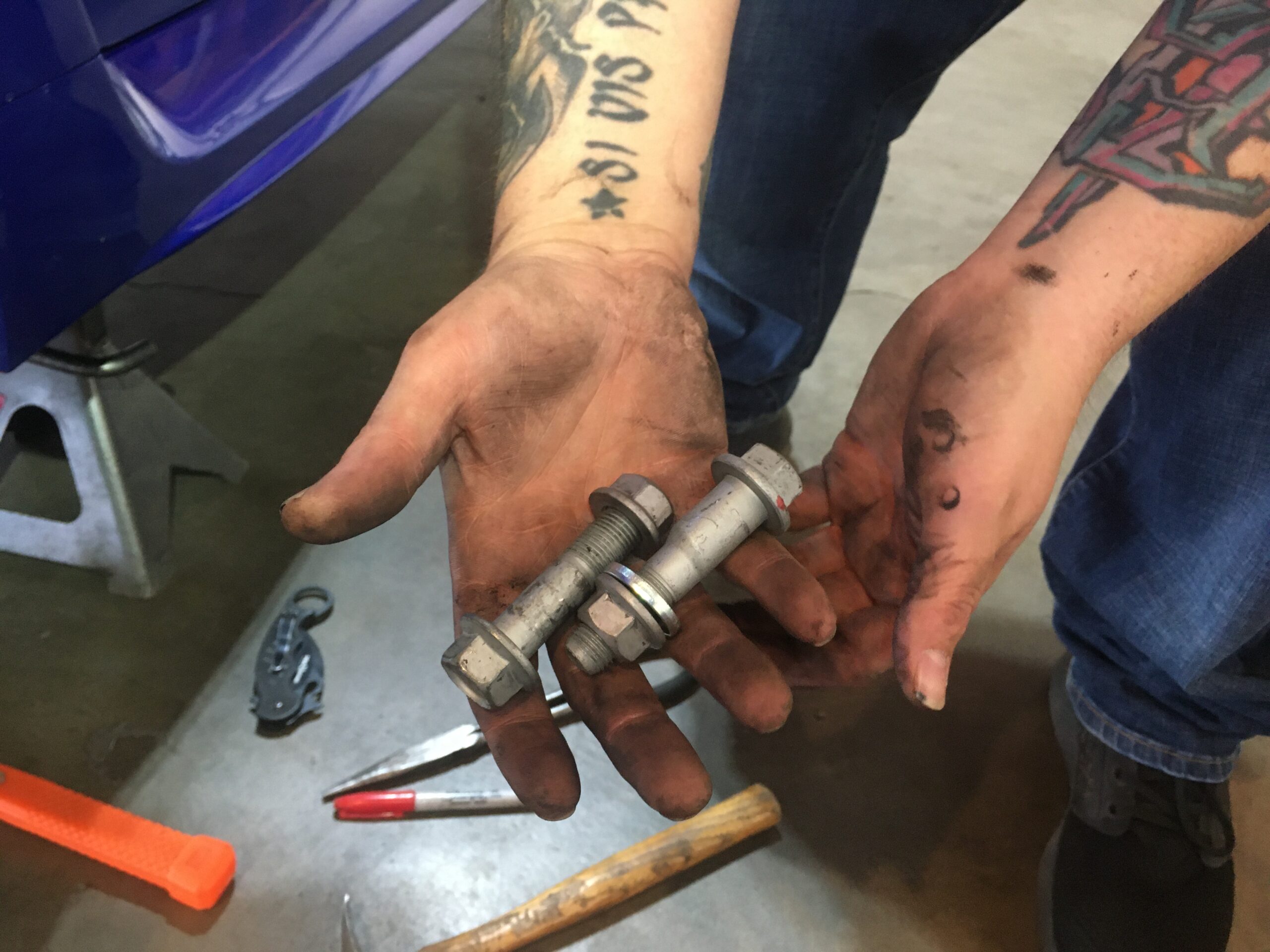
Note the top bolt has the washer and is hub-centric.
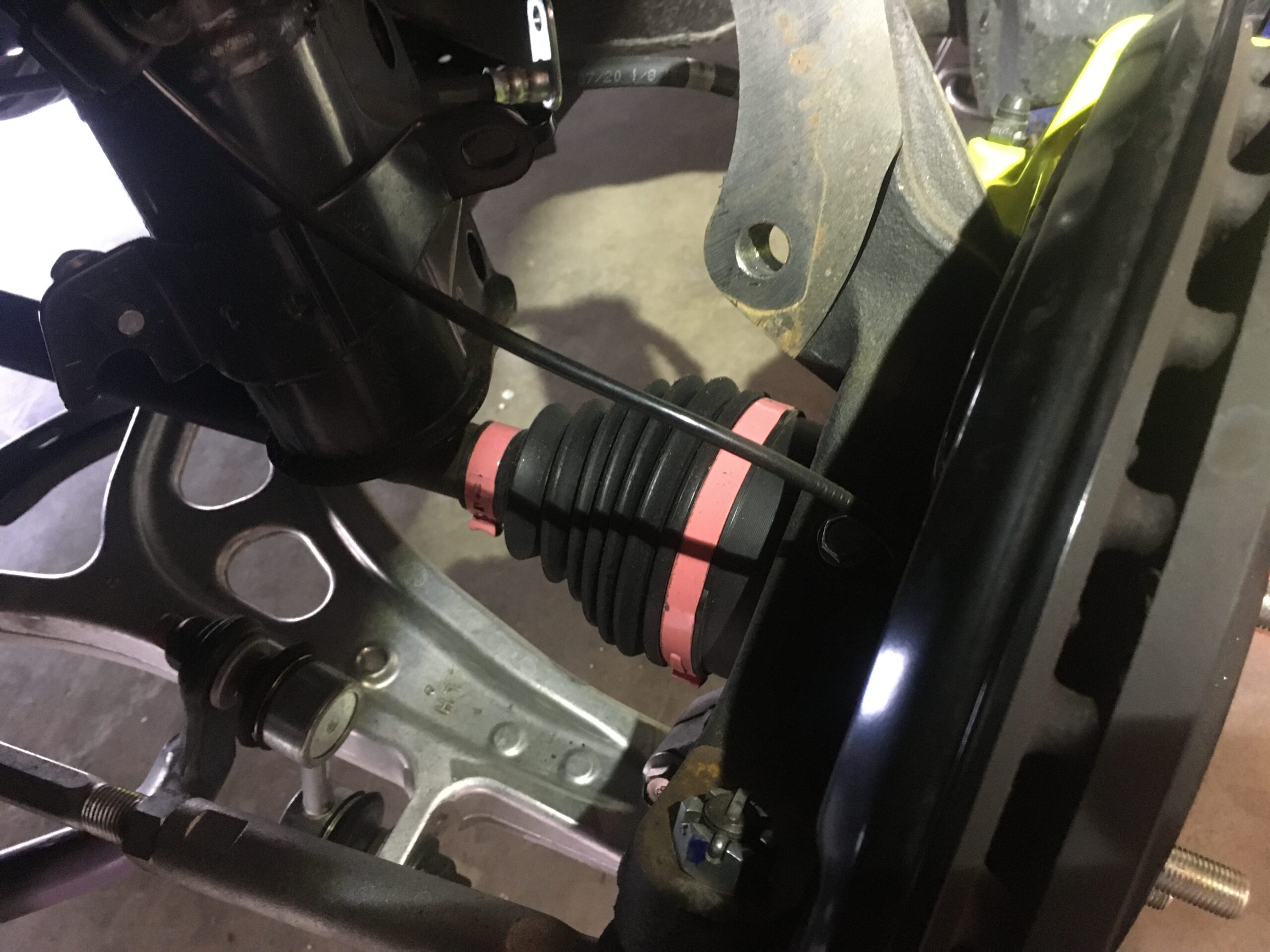
Here we also found a nice sti surprise. “Sti pink” CV Boot clamps FTW.
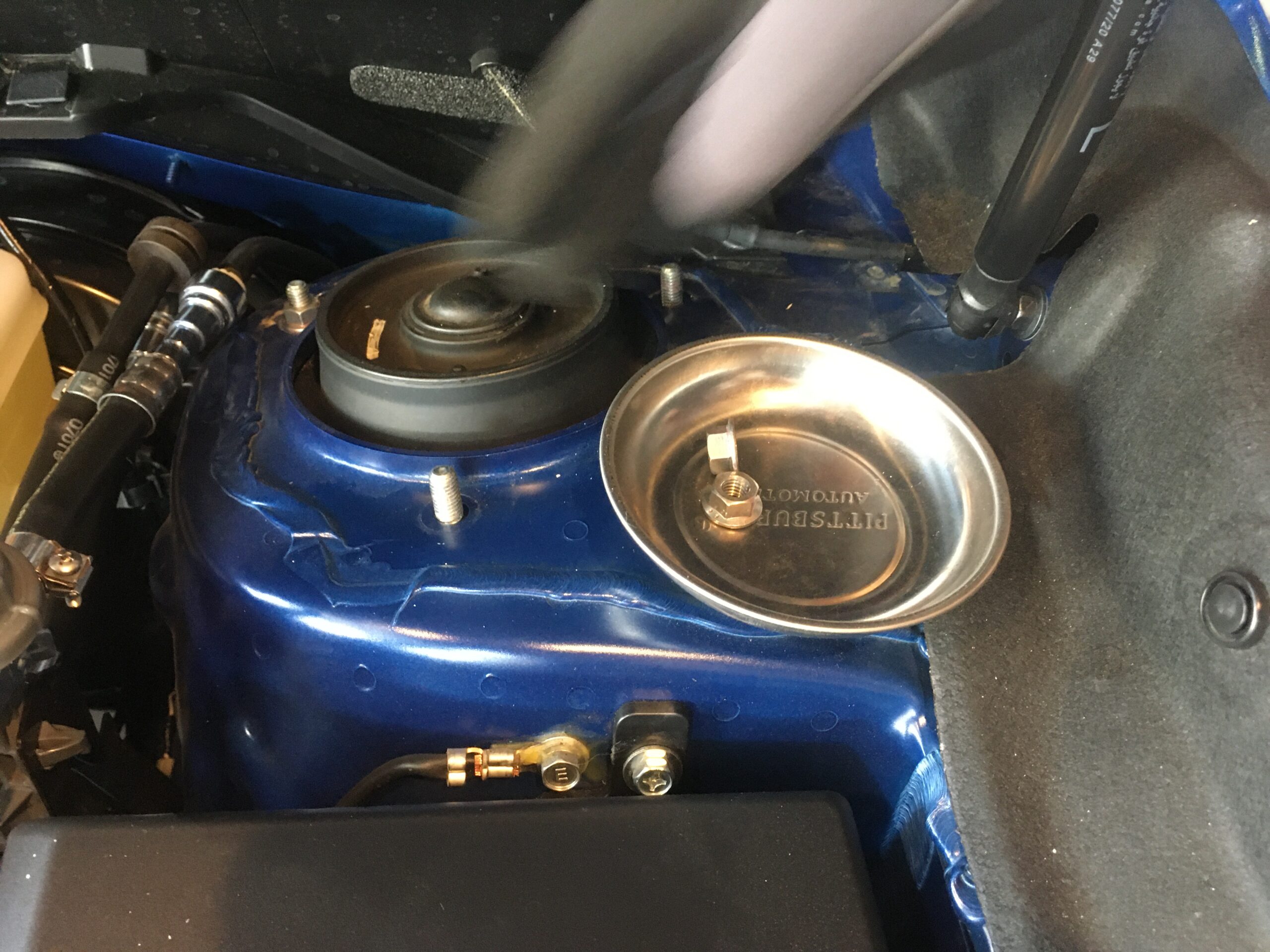
12mm socket and a 3/8 drive ratchet in hand, we moved up into the engine bay. There we found our 3 12mm bolts holding the top struct assembly in place.
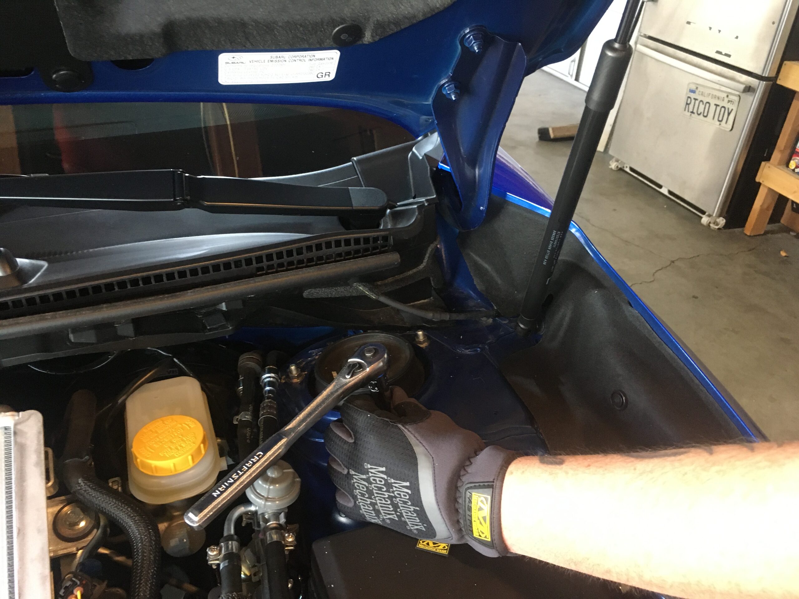
Here is where we utilized our 4″ magnetic parts holder from Harbor Freight for $2.99.
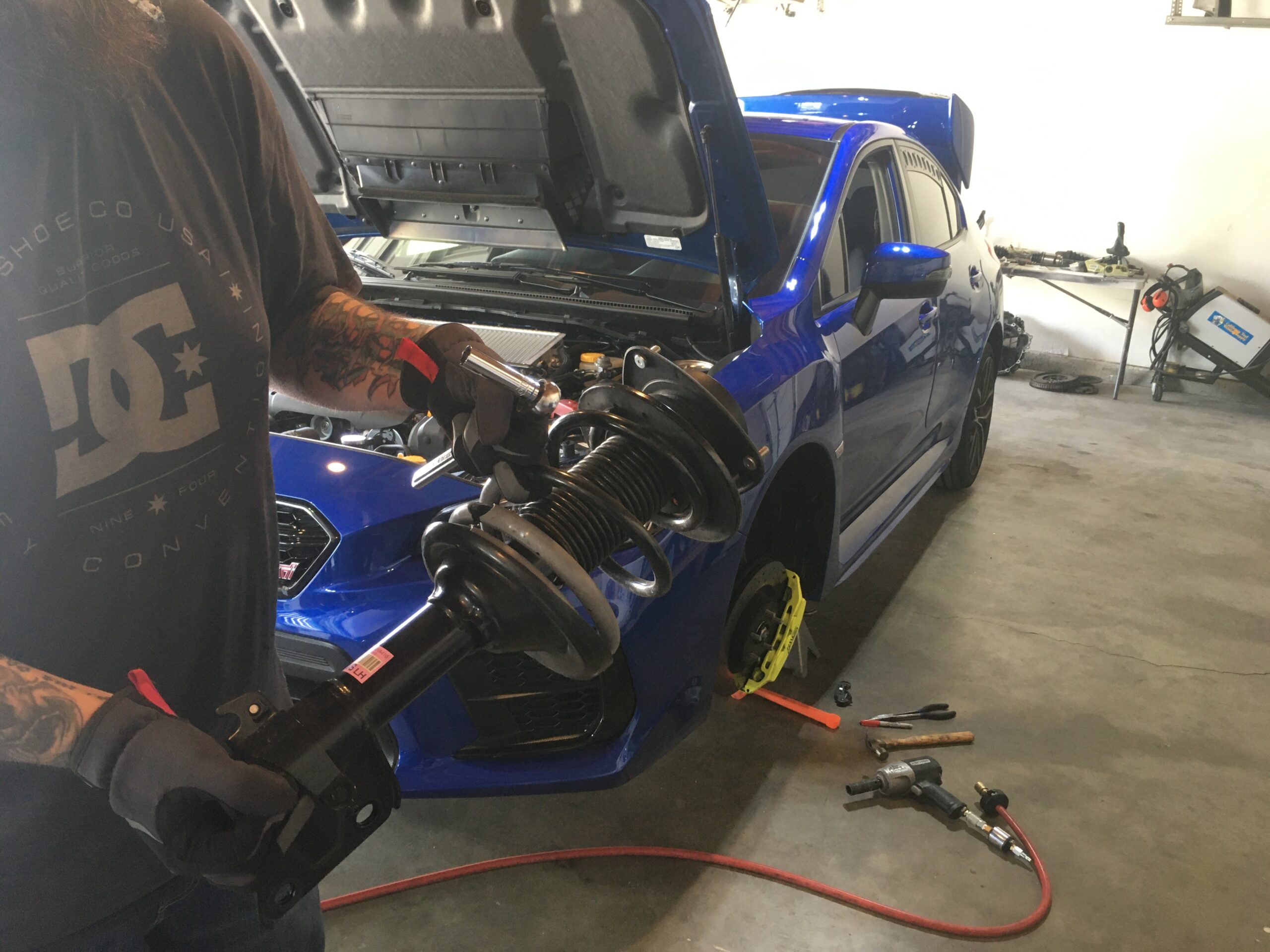
 This is where is was nice to have 4 hands on the project at once. With one person ready to fully release the top bolts, the other is sitting in the wheel well ready to capture and remove the strut assembly without it free falling to the ground and snagging any brake lines on the way.
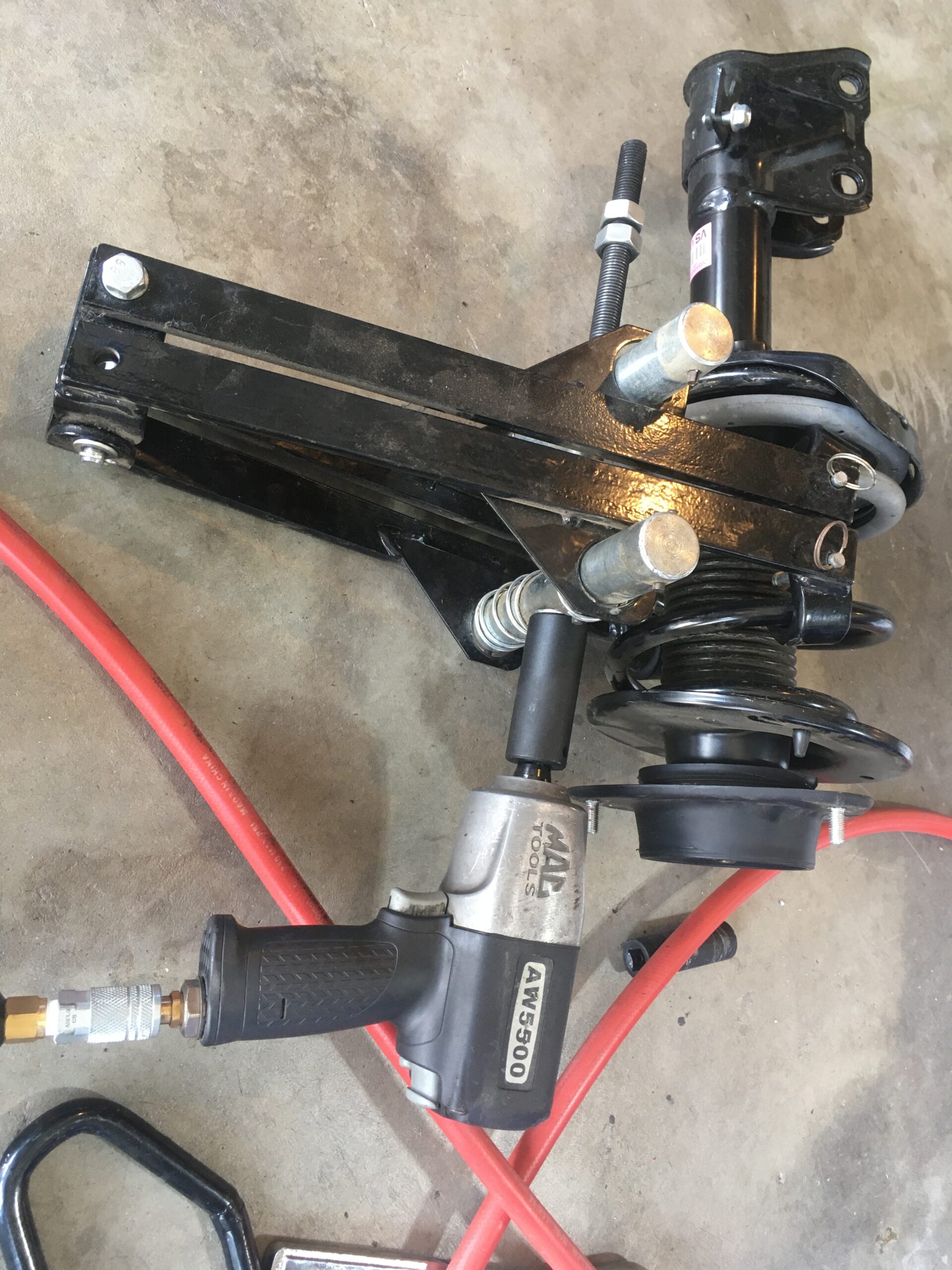
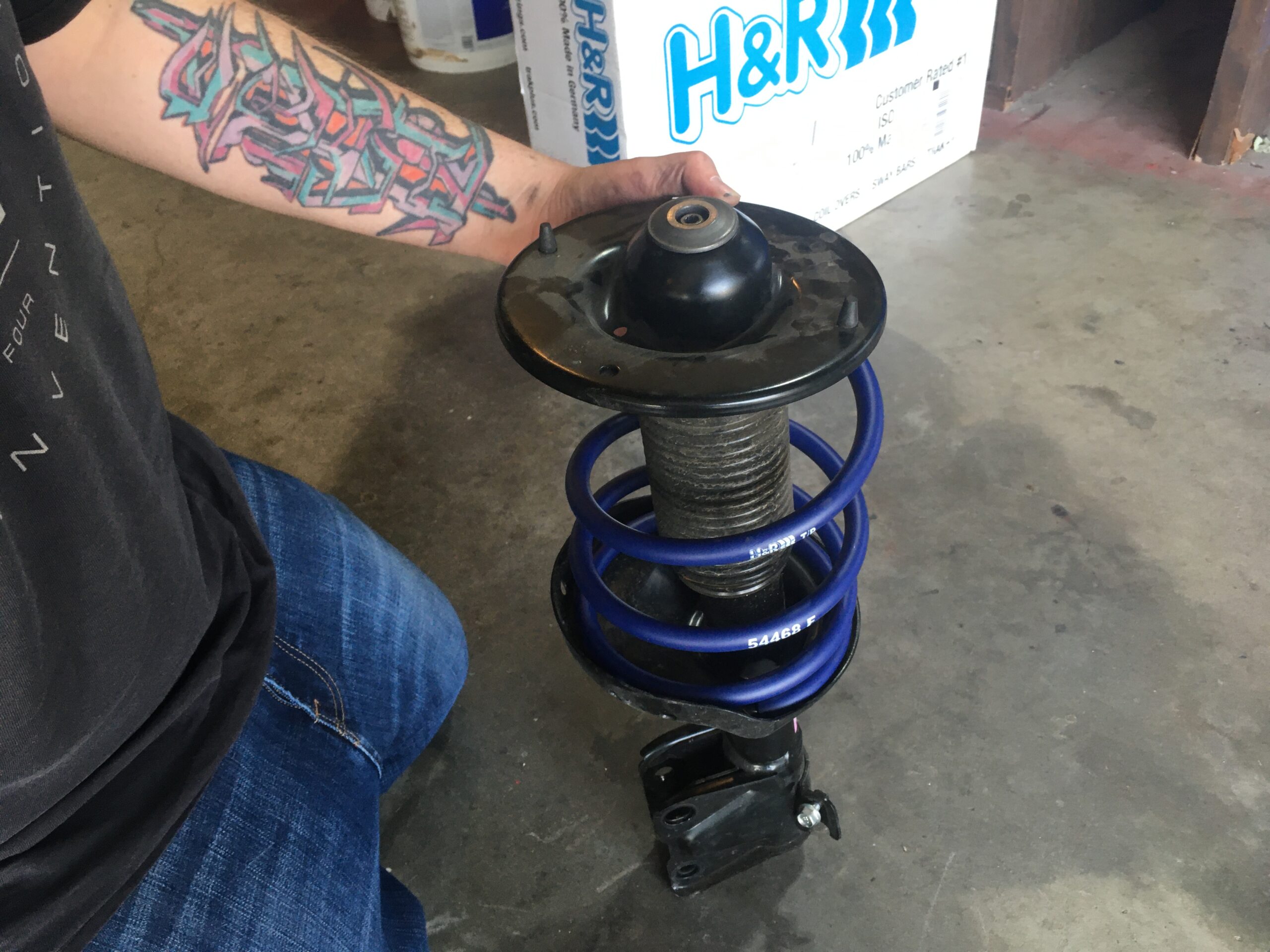
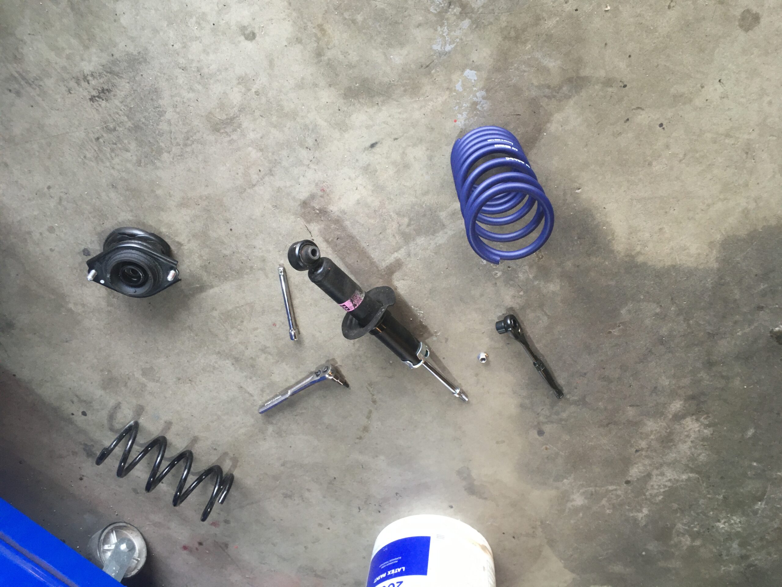
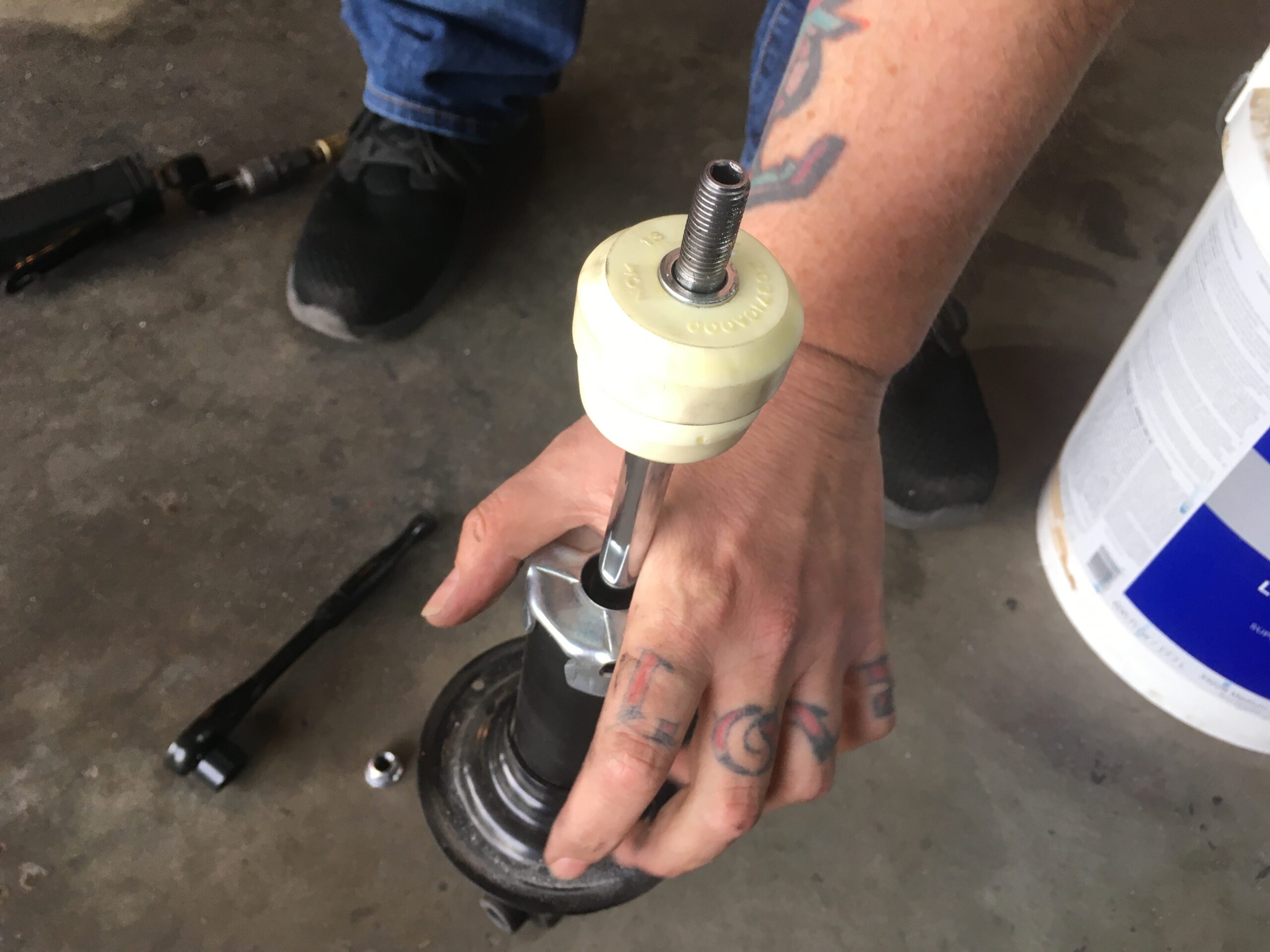
Disassemble strut assembly:
Use a spring compressor, which we found out our heavy duty was too big for these tiny stock springs, compress the spring to remove tension on the strut top hat. Based on some research, the standard rentable spring compressor from your local auto parts store should work perfectly. We maxed out our compressor and it held the spring enough to avoid the old time favorite “coil spring to the face routine”.
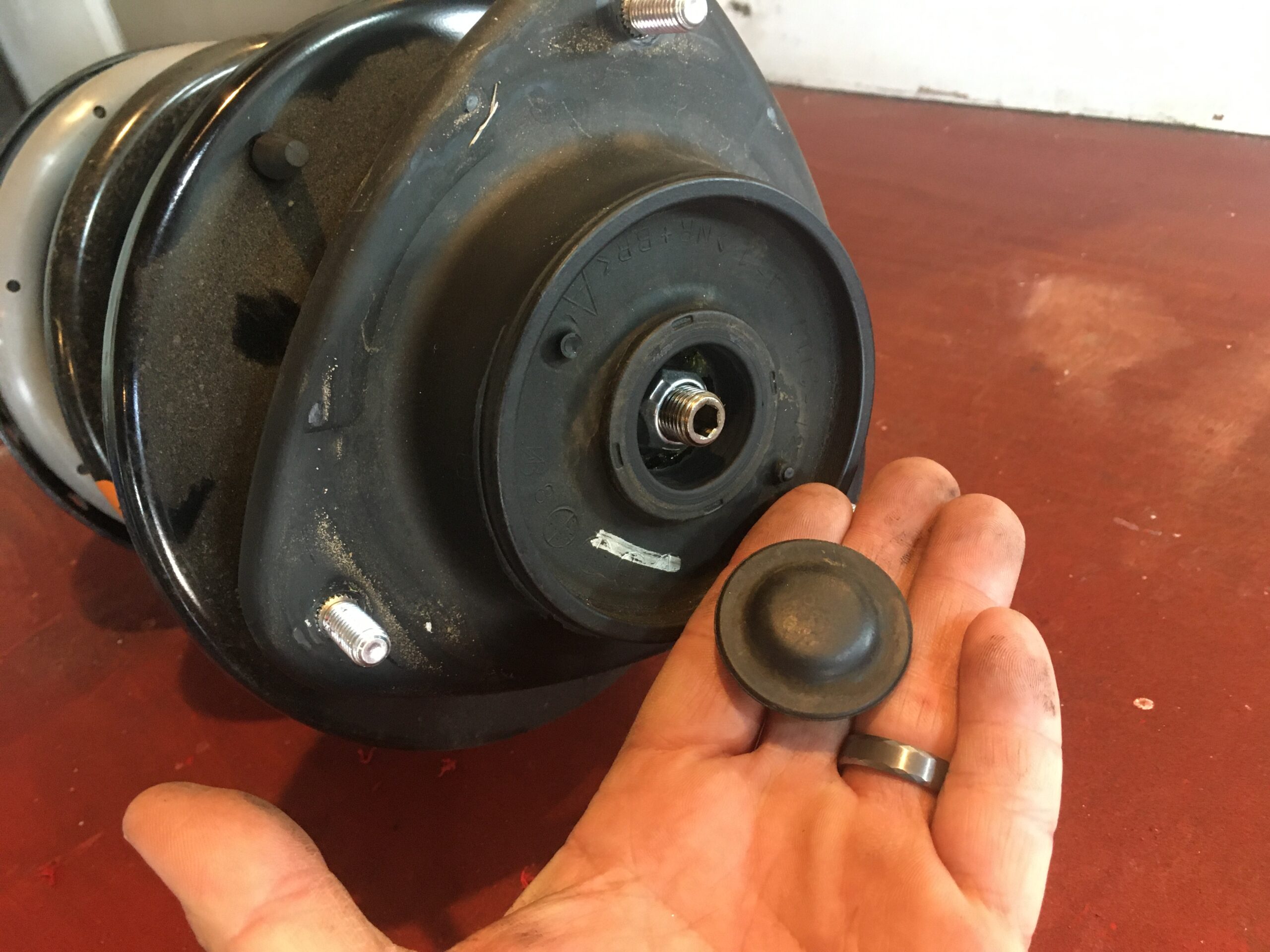
Remove the top rubber cap to expose nut.
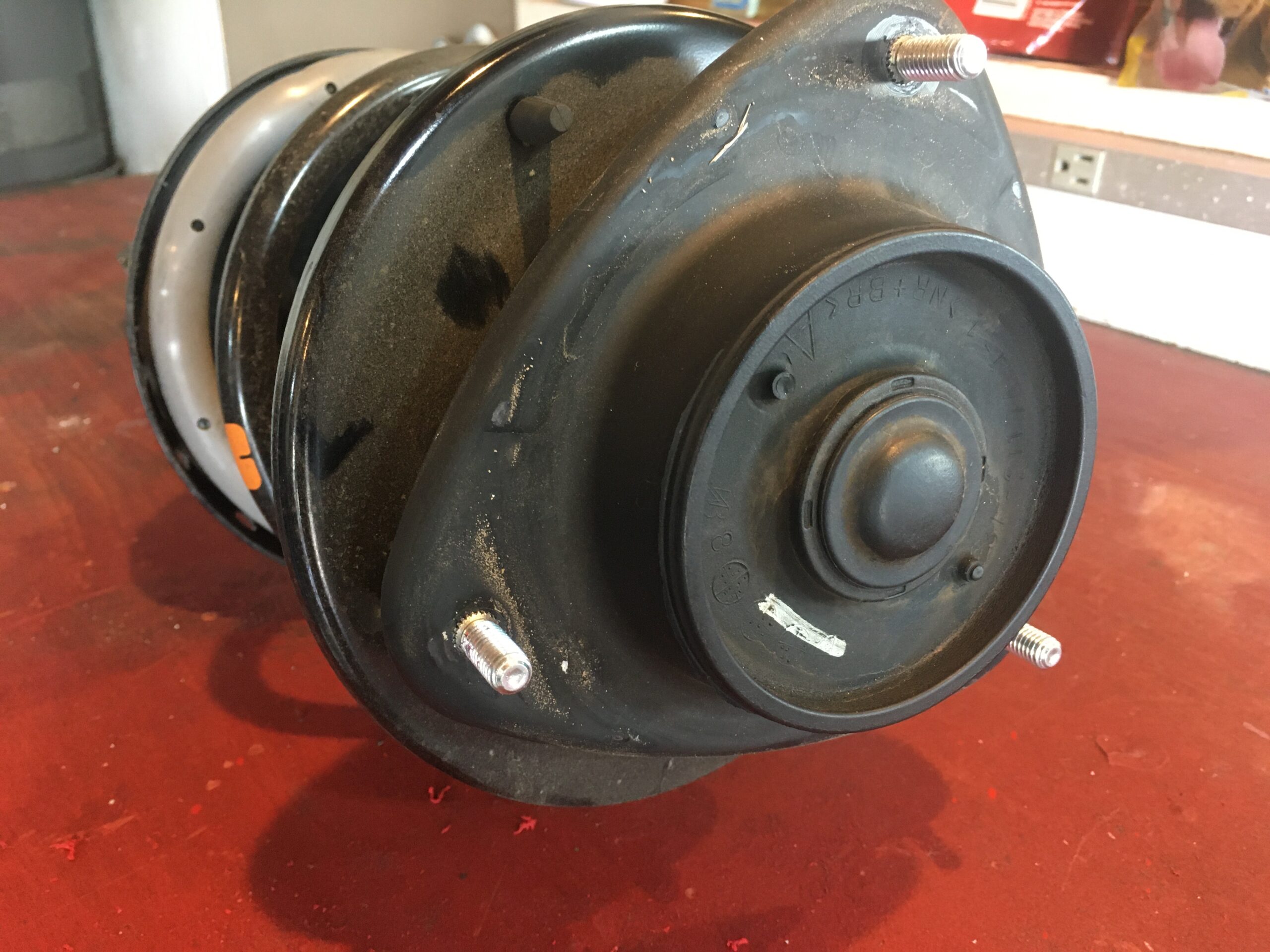
 Pay attention to the alignment of top hat with relation to the lower mount position to try and align as close as possible when you put them back together. We used the little rubber cones as our guide, and noted they were perpendicular to the bottom strut mount.
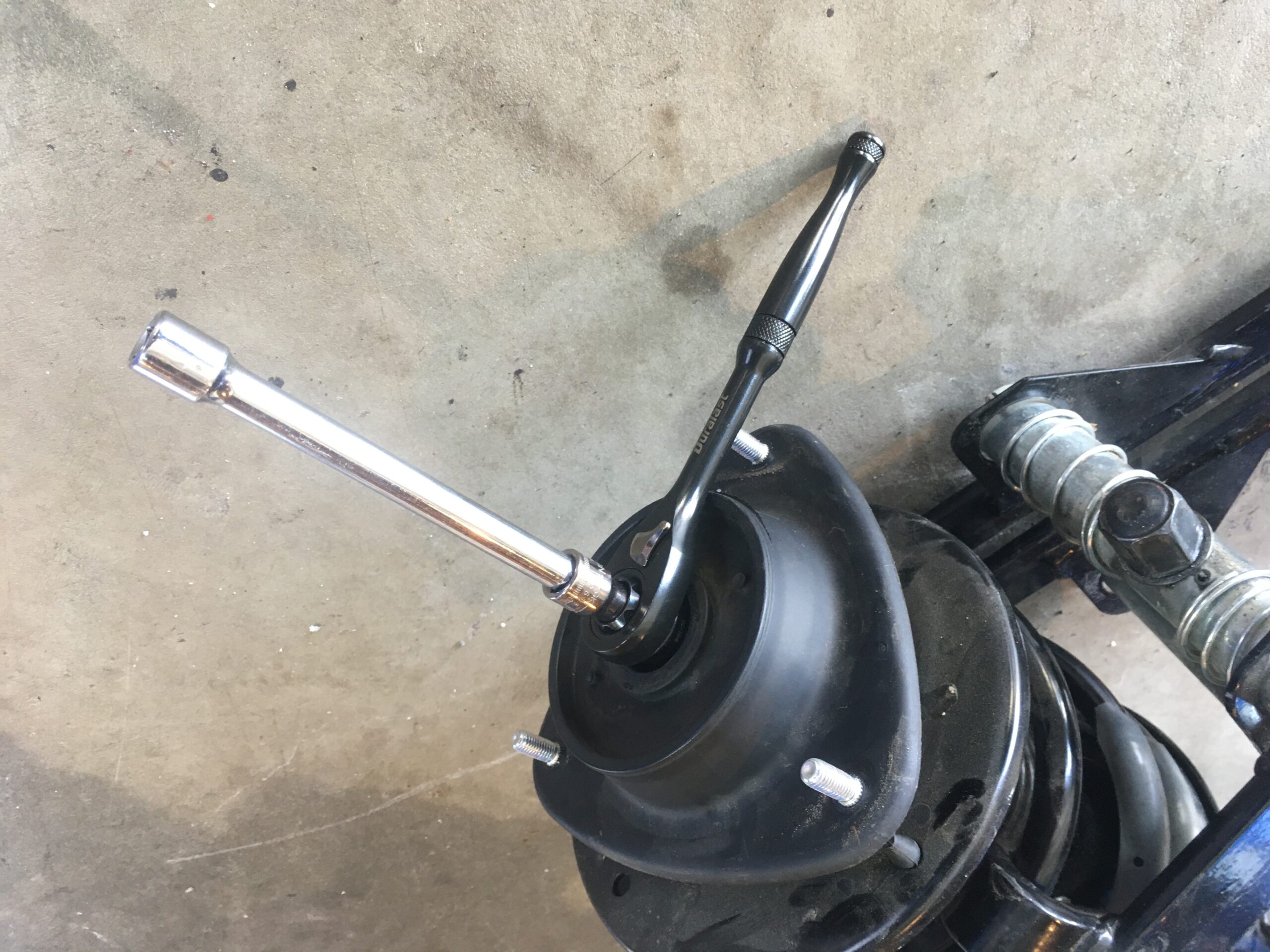
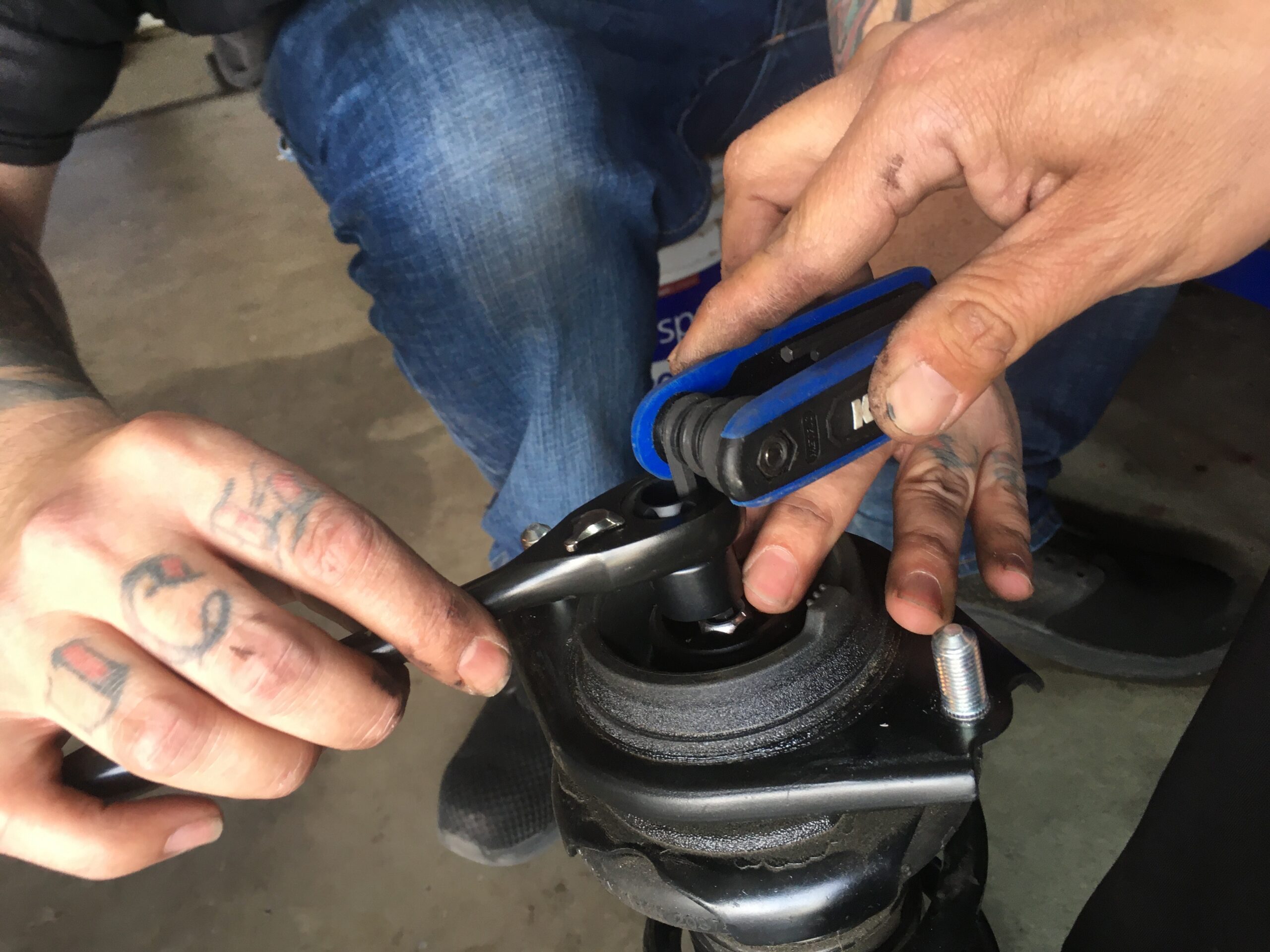
17mm pass thru socket and pass thru ratchet and a 6mm allen socket were the tools used to remove the top but from the strut assembly, freeing the entire unit. We used the Duralast 3/8 drive pass thru socket set from Autozone, which put us back $36.99. With other spring installs we have gotten away with ratcheting wrenches or crescent wrenches, but for this install, the nut was too far recessed for that hack.
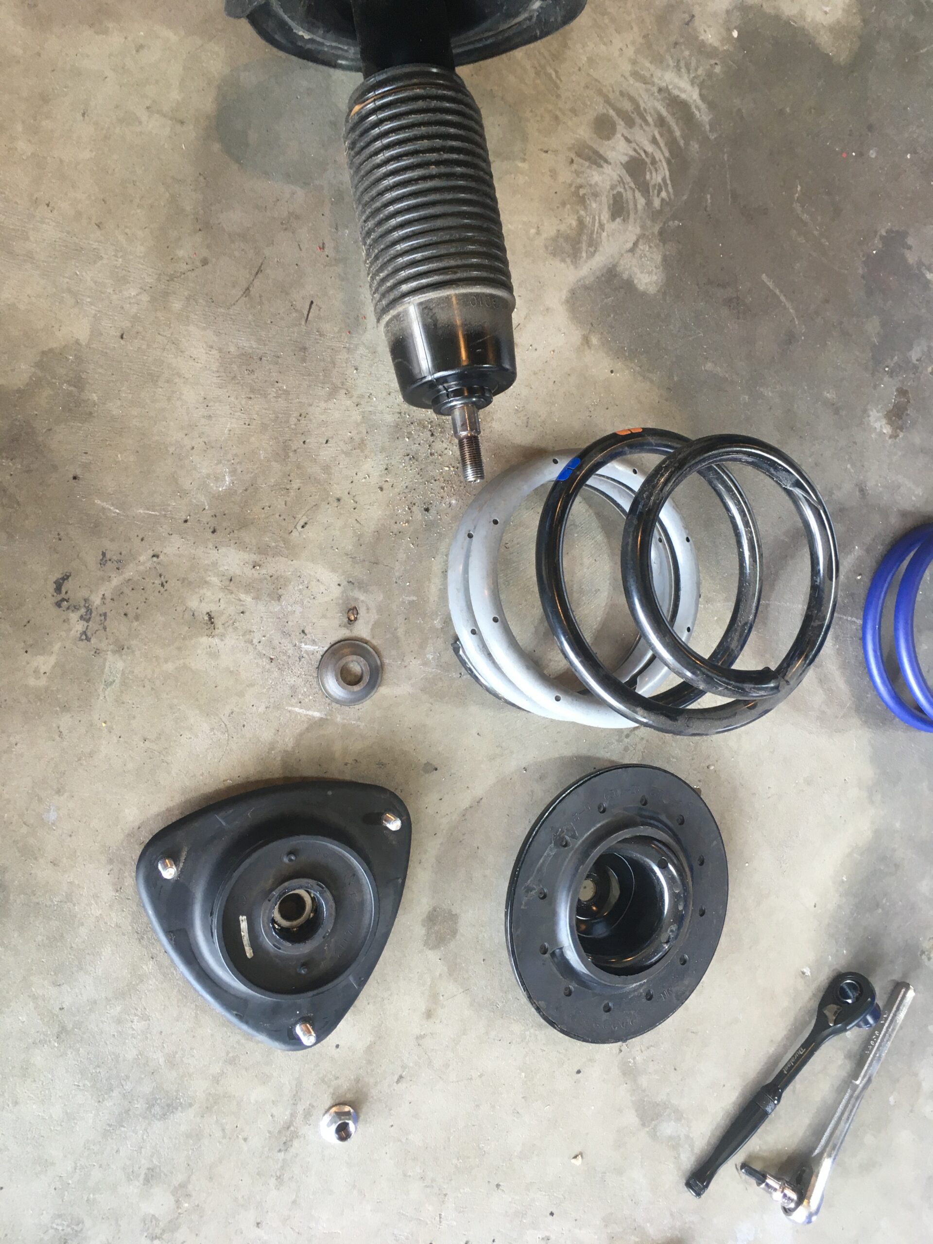
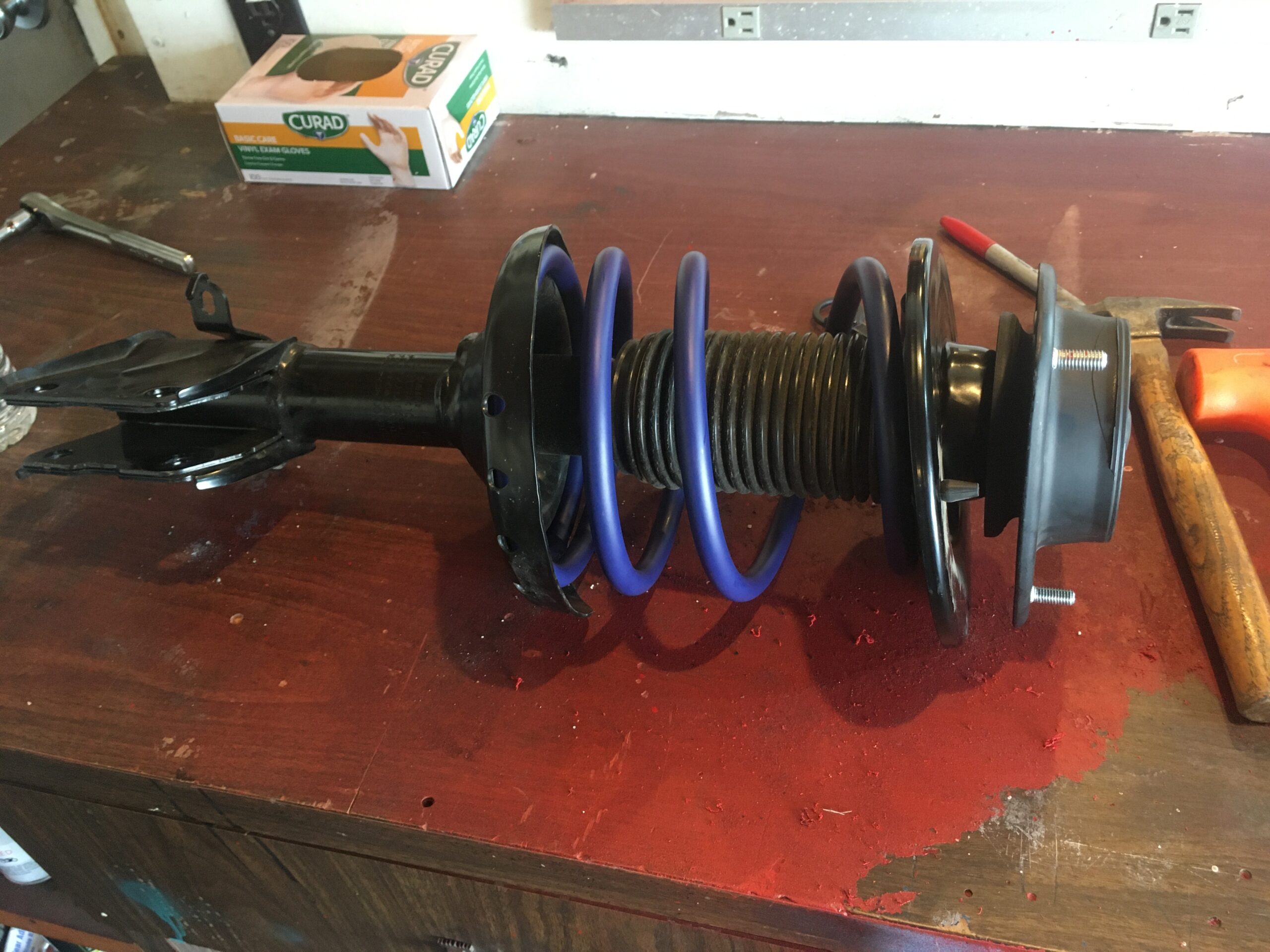
Then you will slide the new spring onto the strut assembly and line it up with upper and lower spring indentations on rubber stoppers/guides.
You (a friend is better, so you can start the but threads) can press down top hat and get starter threads on the nut, then tighten nut back down to end of threads using the same tools you just used to take the top hat off. Factory spec on that is 41 ft-lb.
Replace Strut Assembly
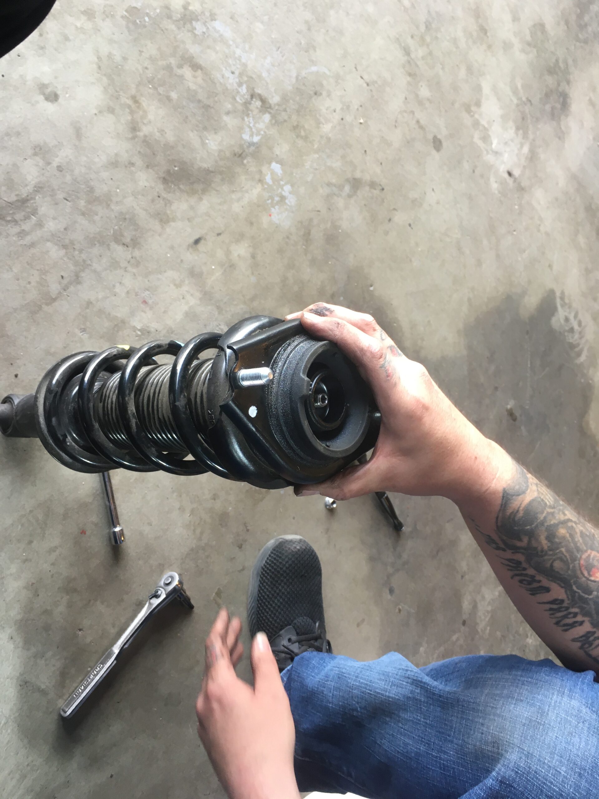
From the bottom, push the strut assembly up. Note in the image below, the factory white marker line on the top hat, the line will be parallel to your headlight, or at least it was on ours, so check that line prior to removal to confirm where your line was orientated. Replace the 3 12mm blots on the top hat. Torque those bolts to 15 ft-lb.
Slide the lower strut assembly back into the control arm bracket, replace lower bolt and nut, place the top bolt and washer in, and line back up your alignment mark and torque both to 114 ft-lb.
Re-attach the brake line and torque the 12mm bolt to 23 ft-lb.
Re-attach the ABS sensor clip by pressing it into the bracket….and you’re done… with one side.
Lower the car and torque lug nuts to 88ft-lb.
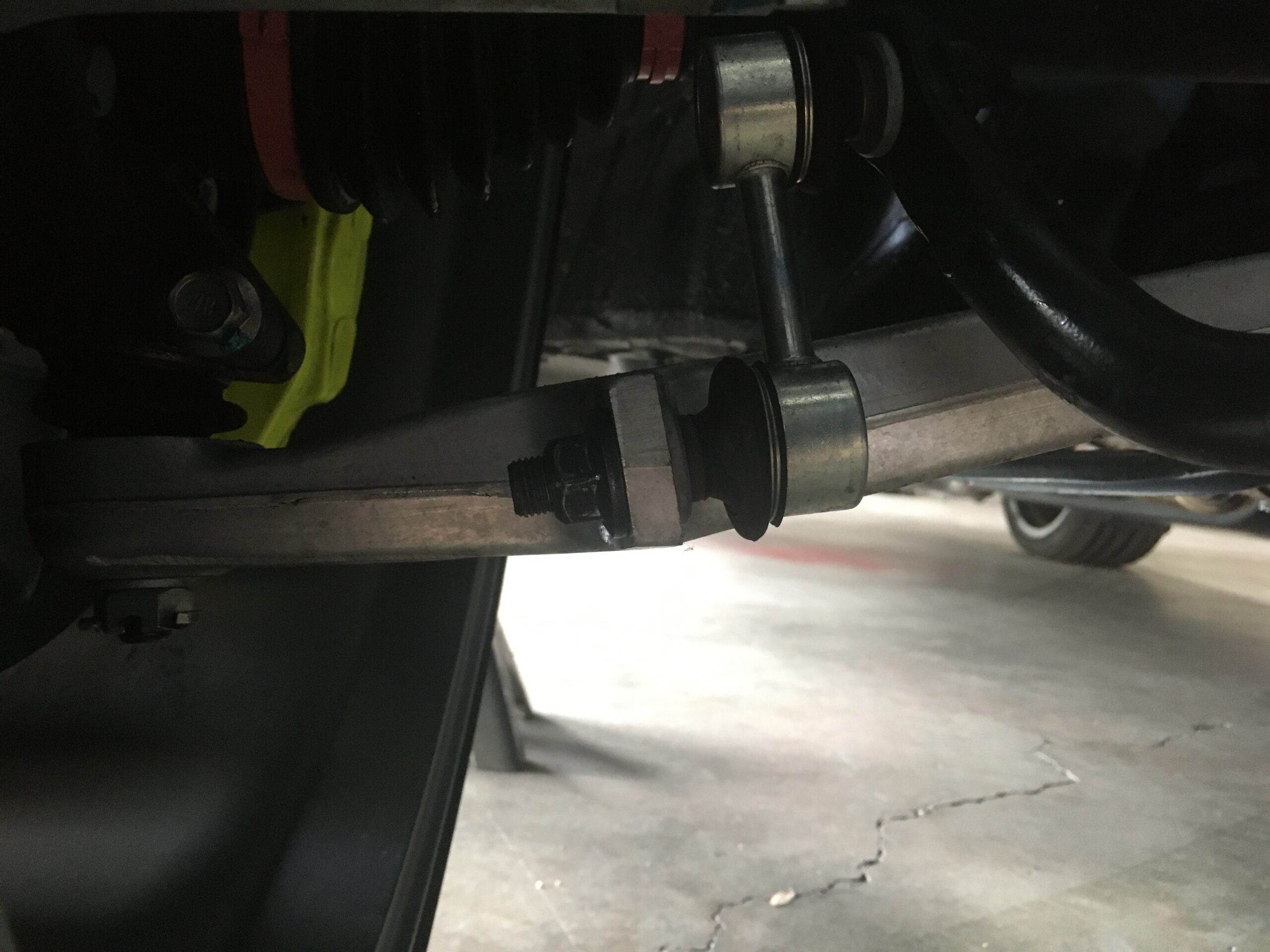
As we said before, we did one side at a time, so when we attached the passenger side we had one issue. The lower bracket wasn’t lining up, and we were real close to mashing our strut lower brackets into our CV boot. This was probably due to changed stance and load from the new spring already installed on the driver side, and further than the driver side was already back on the ground.
We removed the lower tie rod end with a 17mm socket and 1/2 drive ratchet to drop the bracket and strut into place. After the strut assembly was fully torqued down, we then jacked up the whole control arm assembly to align the tie rod hole, and then suited that nut back up to 28ft-lbs.
Hitting the Rear
For the most part, same as before…break 19mm lug nut bolts while car is one the ground.
Jack up the car and secure the car down on your jack stand with enough clearance to pull the wheel off.
Completely remove the lug nuts and wheel.

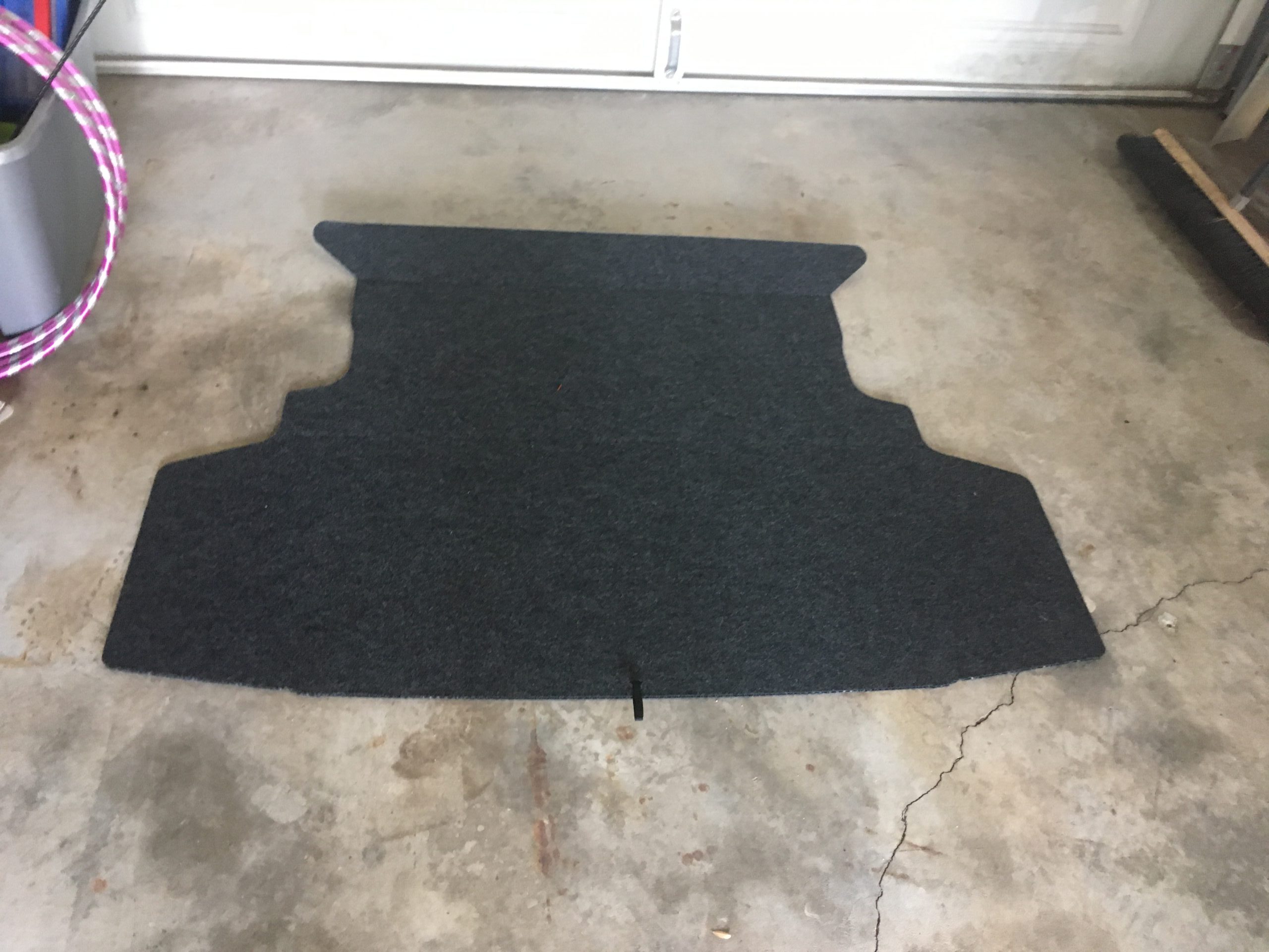
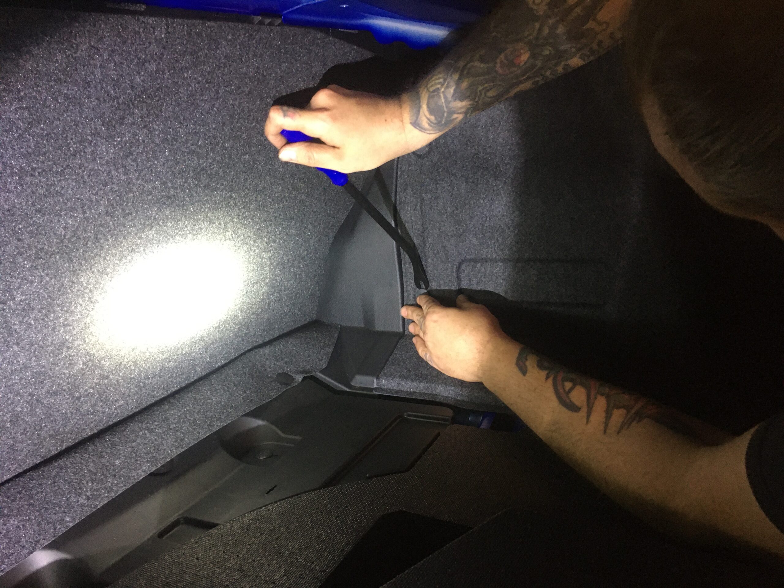
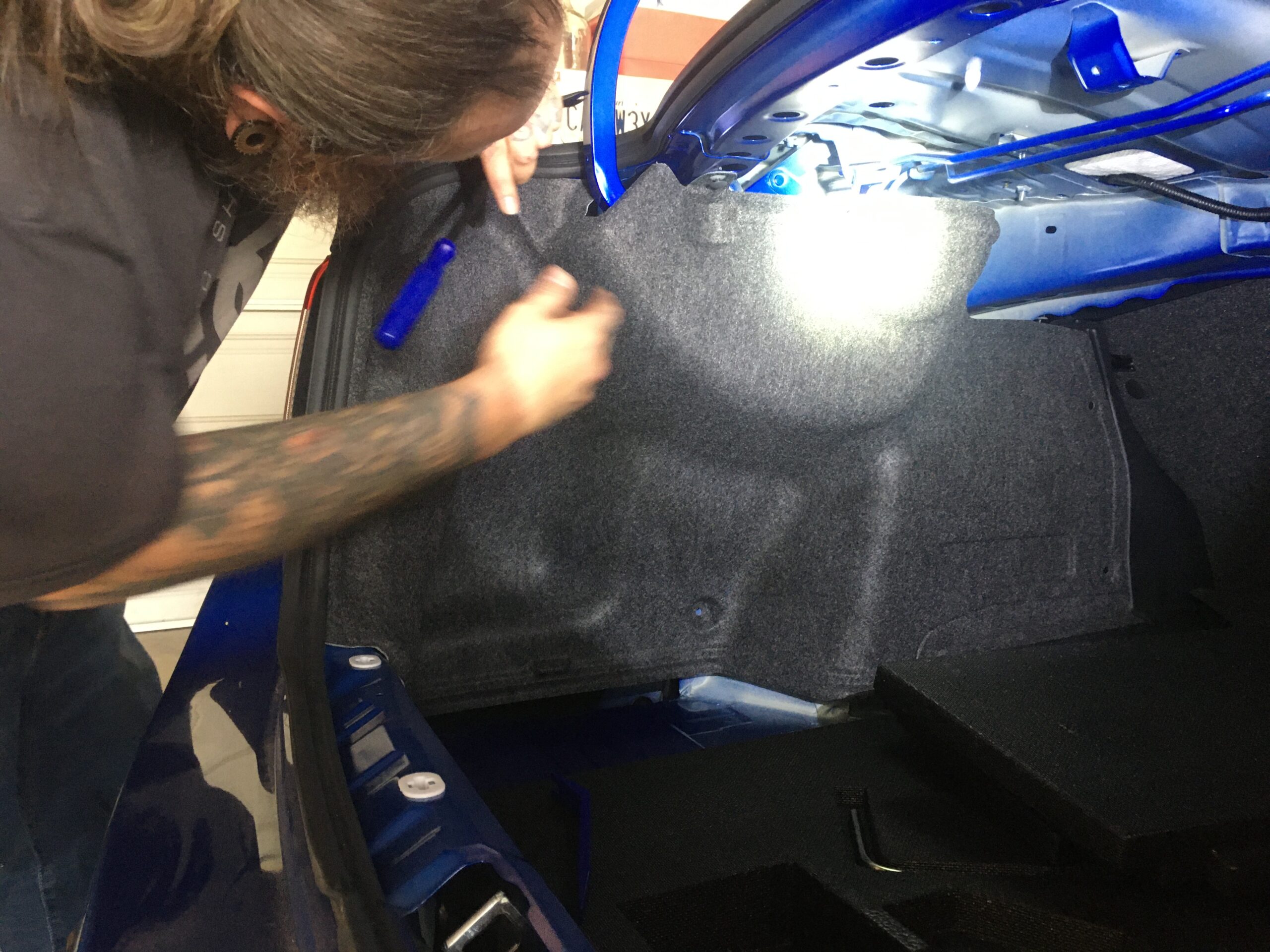
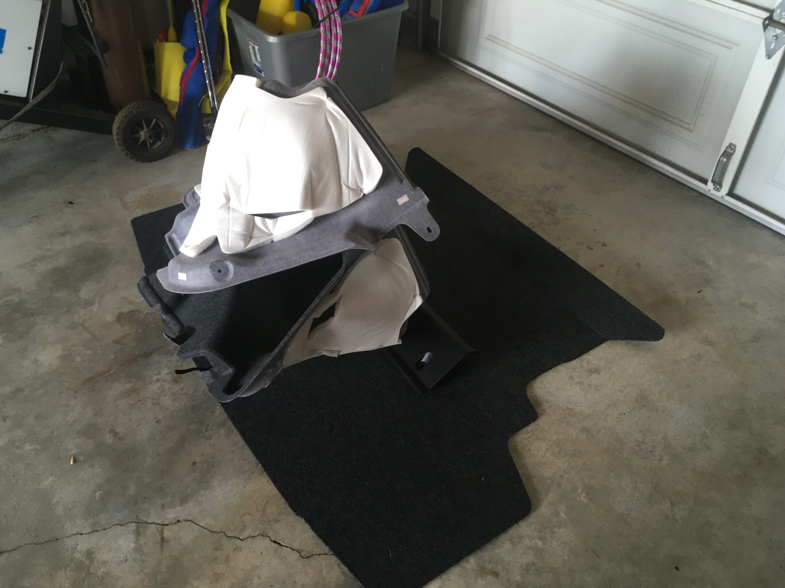
Now we move to the trunk to dig our way to expose the top strut mount bolts. Pull out trunk carpet pad. No special tools needed here.
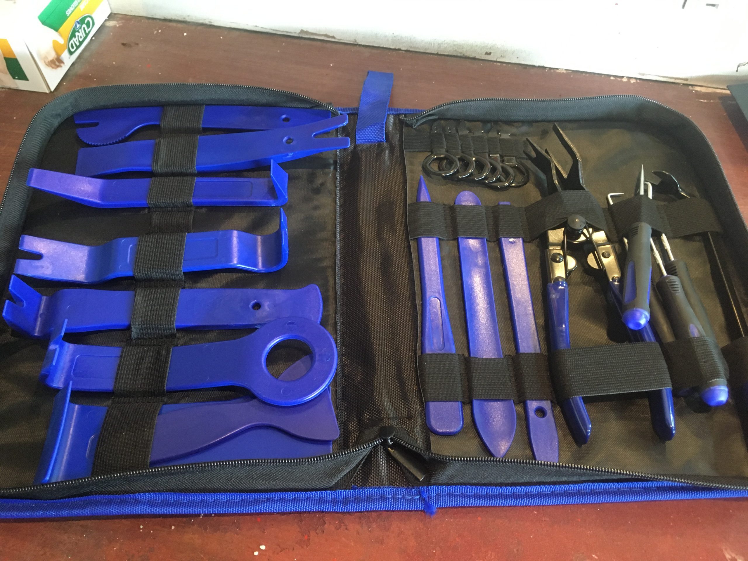
For the next set of steps we had to remove the right and left interior panels. We used the Dualeco Trim Removal Tool Set we picked up on Amazon for $26. We’ve also used this kit a million times on door panels and other interior pieces that needed removing. It allows you to pull trim retainers without breaking them. For the most part, you can place the trim back in with a few broken clips, but for those of us with OCD, and really want maximum re-sell value, this tool saves you trips to the dealer for $4 clips.
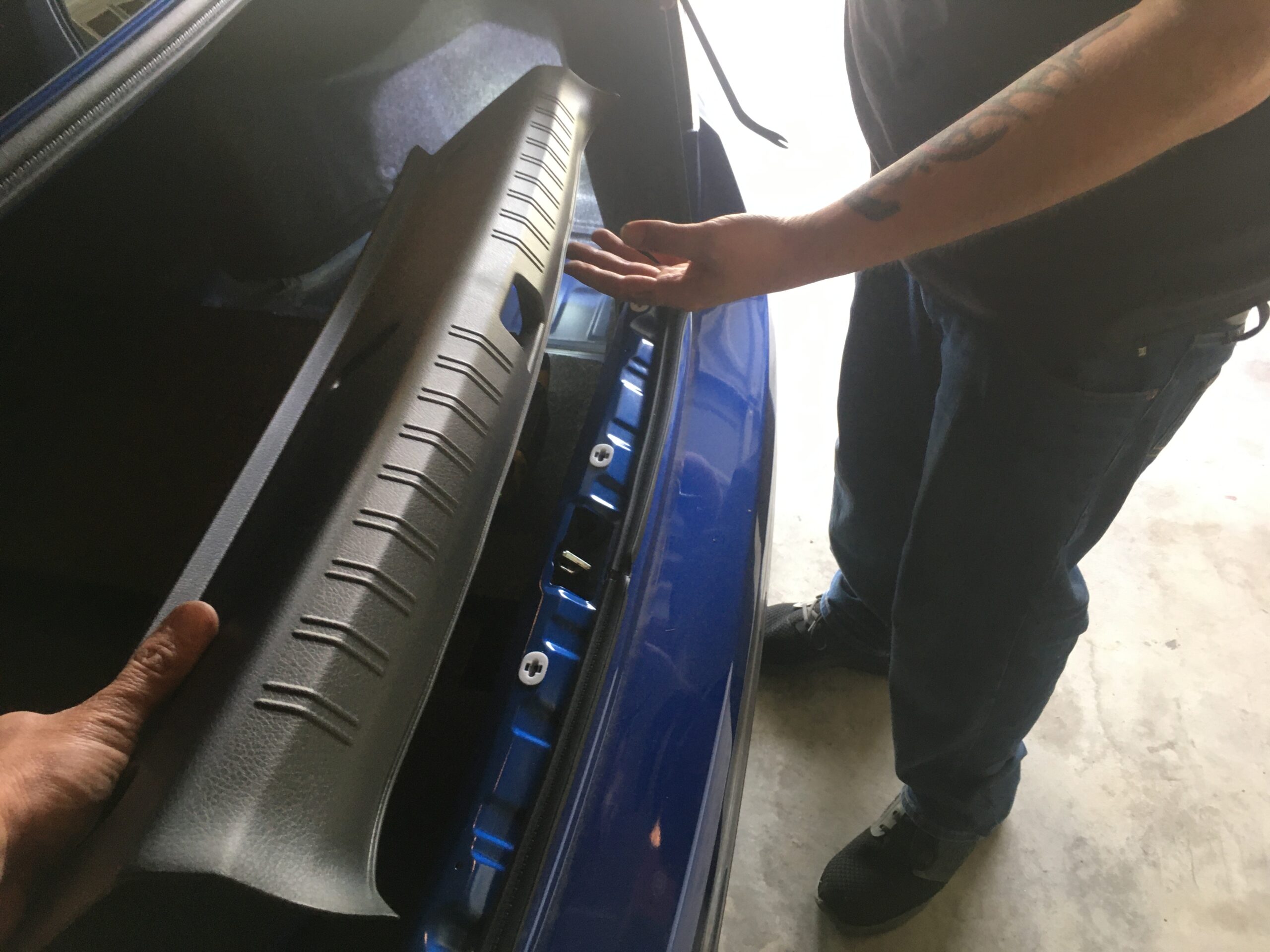
Start by removing the trunk lip trim piece. There are 4 plastic push clips. Our panel retainer removal tool worked awesome, but you can also pry these off with a flat head and some needle nose plyers.
Now we have to pull the driver and passenger side trunk side carpets. Each one has 6 push clips, at which our tool also made quick work of removal. Get low and look up to find the clips that are fully vertical, find them near the trunk hinge bars.
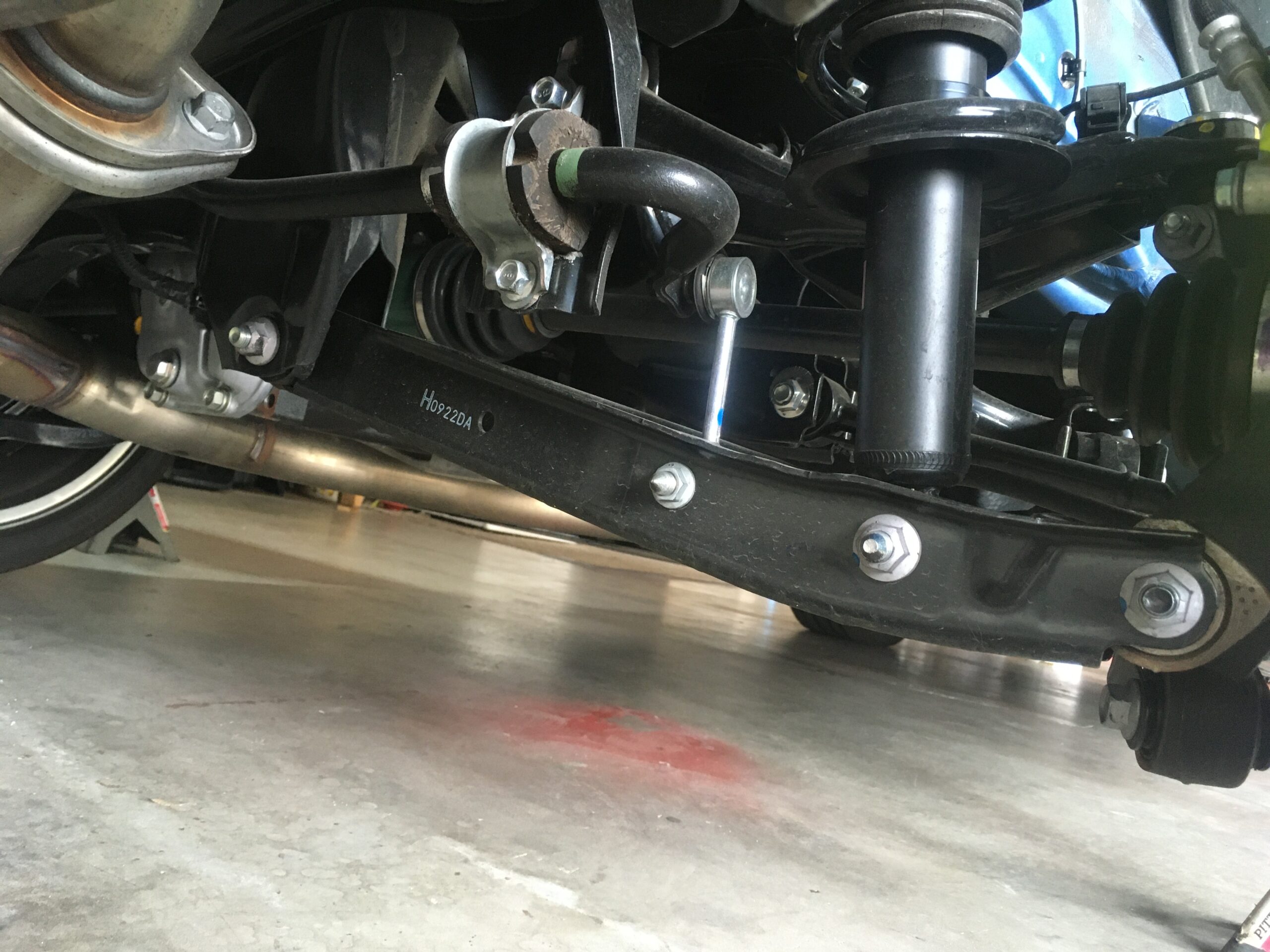
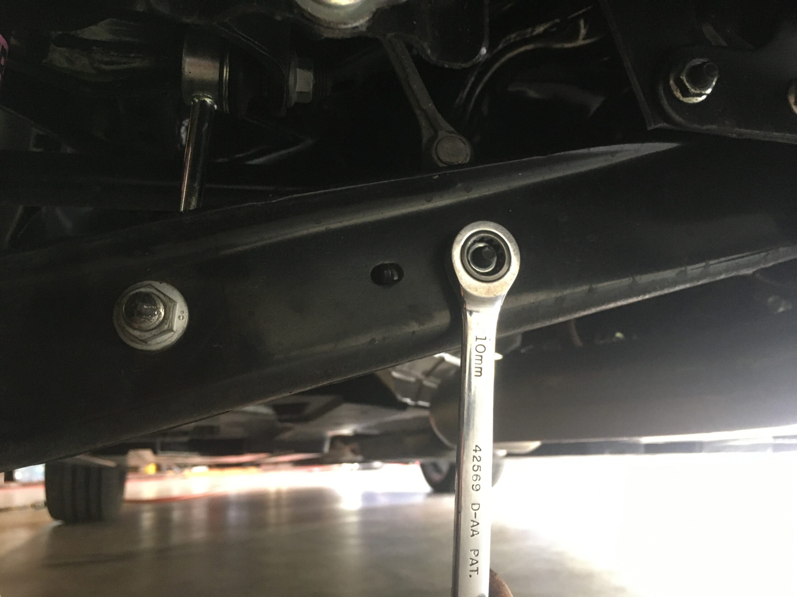
Now that you have all the trim out you can get started on the real hardware. The lower control arm has 3 bolts on the passenger side, and if your model has leveling headlights, you will have 4 on the driver side. These are 2 17mm nuts and bolts, a 13mm nut and bolt and a 10mm bolt on the driver side for the headlight level sensor on the driver side.
These nuts/bolts will spin the corresponding nuts/bolts, so this is where your backup set of ratcheting wrenches or sockets will come into play to stop spinning and let you fully remove these nut/bolt combinations.
Here, on driver side, on models with the leveling headlights, you will see a 4th bolt to remove that hold sensor, again, 10mm ratcheting wrench or socket will do the trick.
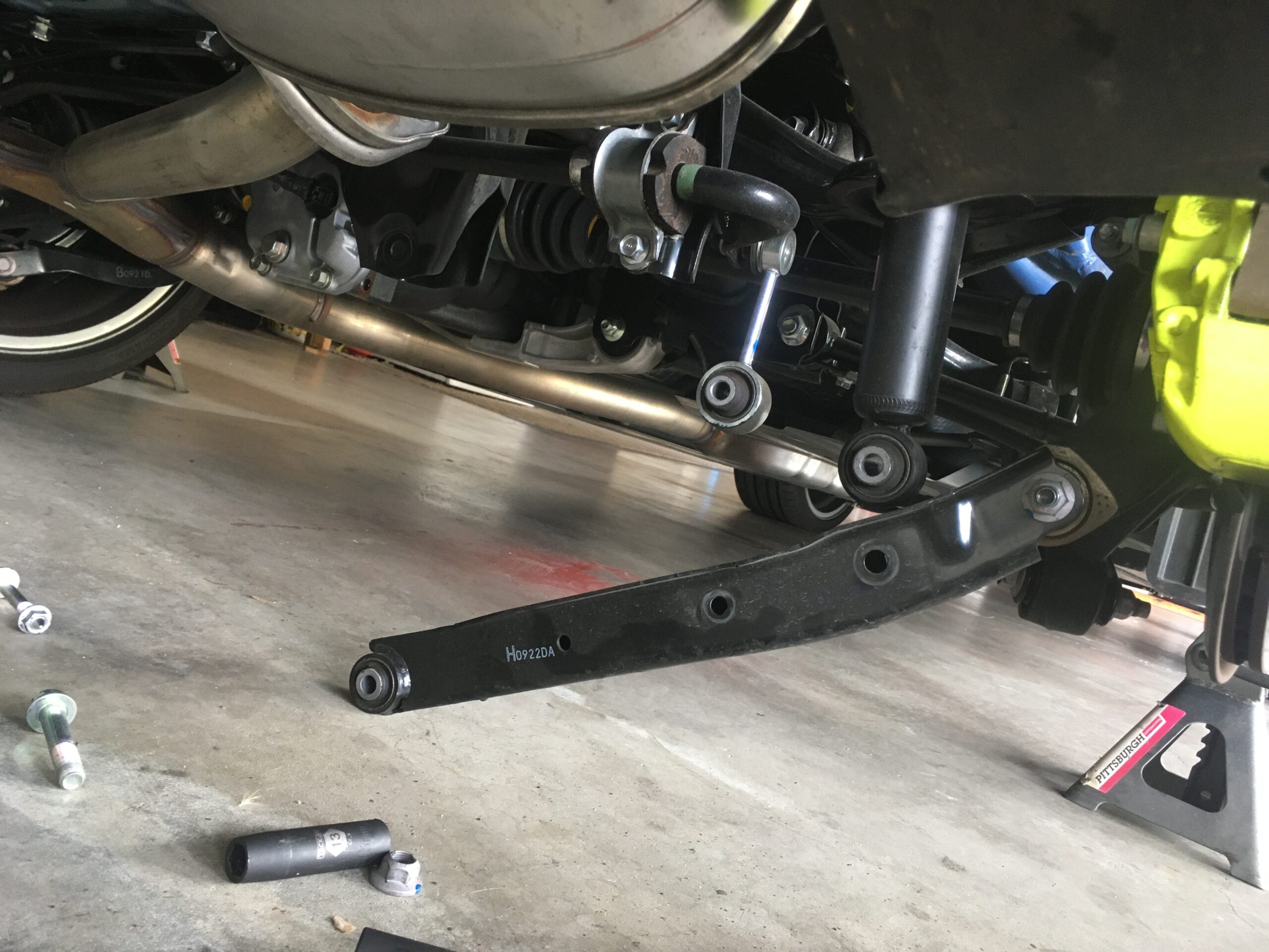
The nut and bolt combination closest to the middle of the car is a little pinched as the exhaust pipe is in close proximinty, so here we used a swivel socket extension to gain access.
These bolts still have some tension, so you can knock those out with your extension and rubber hammer.
You will leave the furthest bolt that attaches to the bottom of the control arm in place. Once all bolts are out. the link arm assembly will swing down from wheel hub assembly.
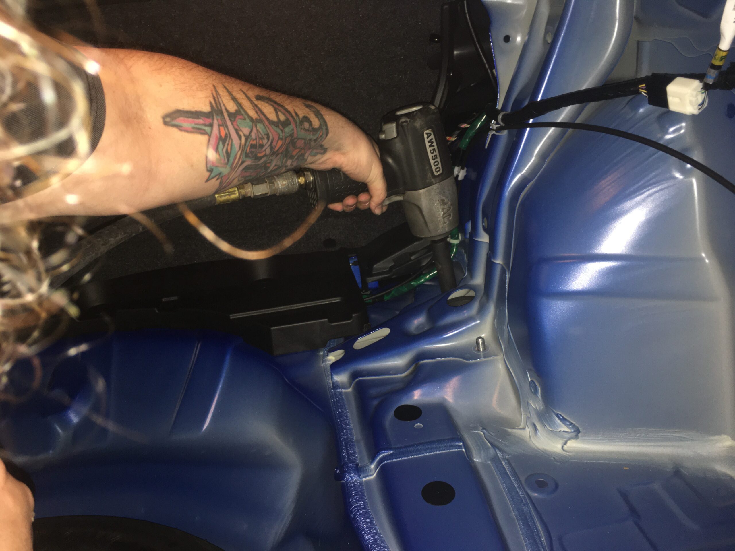
Now you can move up top…. and by up top we mean in the trunk. There are 2 bolts that hold the top of the shock assembly to the body. These are both 14mm. We hit it with our MAC air gun for ease.
Same as the front, a second set of hands in the wheel well will make it easy to pull the assembly out without a freefall.
Removing the spring from the strut assembly is almost identical the the front procedure…but you will use a 14mm pass thru socket and a 5mm allen. We found there was no real tension on the spring, so we did not use the spring compressor and simply started pulling nuts.
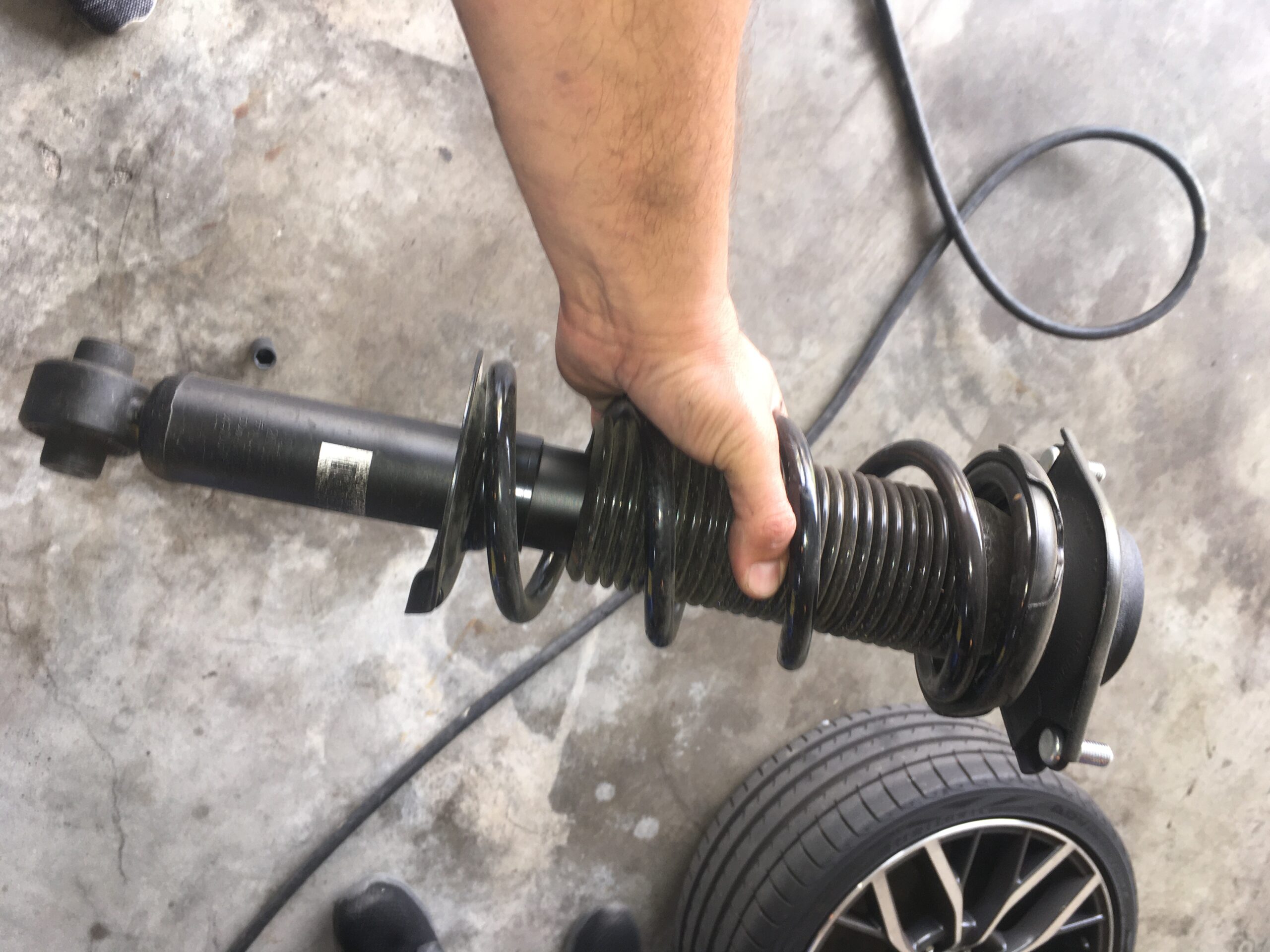
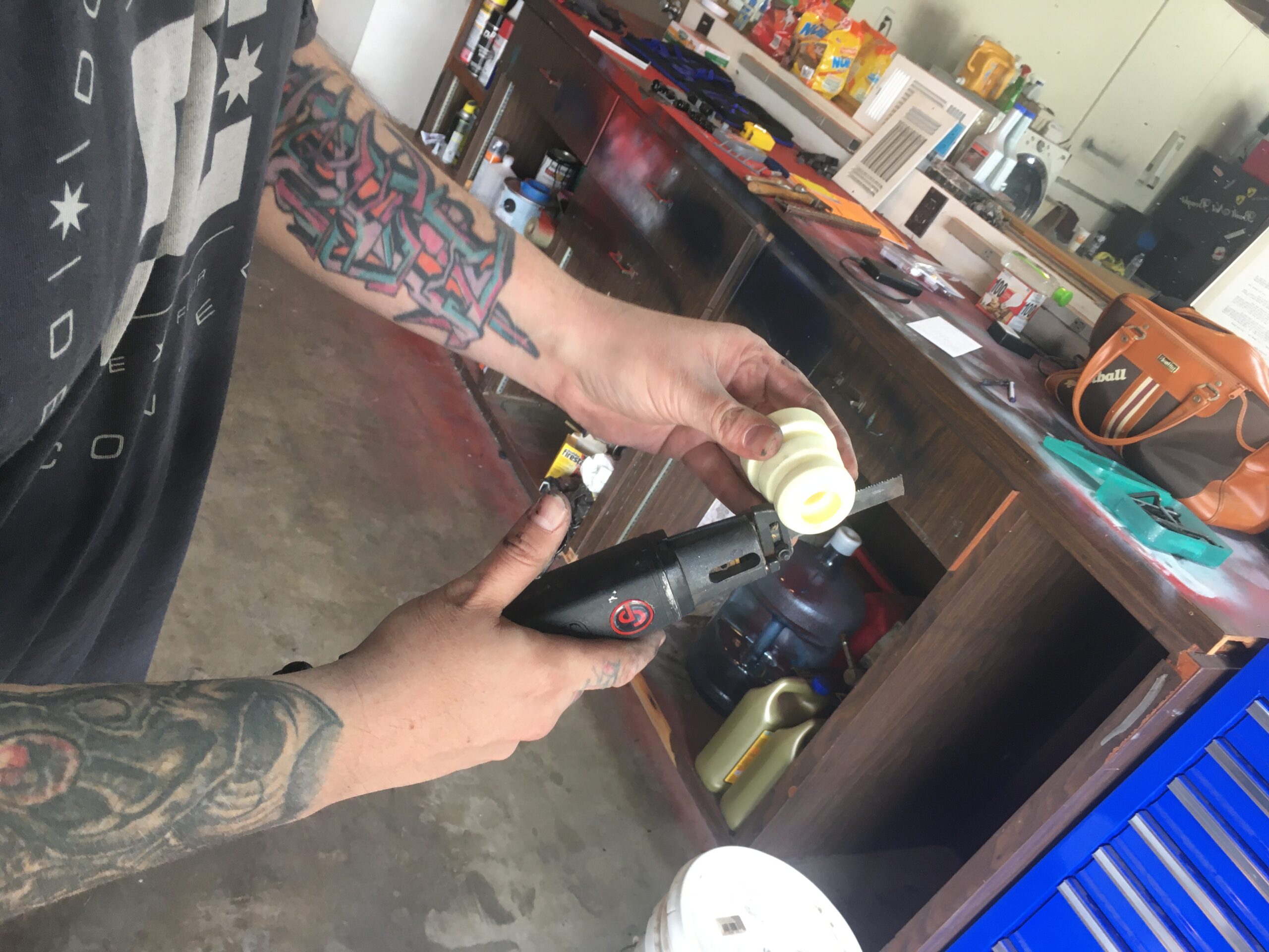
The rear struct assembly does have a foam bump-stop which you will need to cut and remove 20mm from the base to allow clearance. We made quick work of this with our body saw, but a hack saw, Dremel or even kitchen knife would work.
Remove and replace the spring with your new spring and then reassemble the entire assembly in reverse order. The torque spec here is 18 ft-lb.
Now you can put it all back together.
Slip in the strut assembly and hit the top hat bolts in the trunk to 22 ft-lb.
Hop inside the wheel well and hit the lower strut assembly to the control arms to 89 ft-lb.
Place the bolt for the control arm to the sub frame at 59 ft-lb.
Tie rod ends to the control arm will be 33ft-lb.
Replace all trunk trim and carpet.
Put your wheel/tire back on and place your lug nuts back on.
Lower the car and torque lug nuts to 88ft-lb.
No, to balance out the ride and let the suspension settle back into place, drive the car around the block to level out the springs.
We chose not to do alignment since we didn’t have to tug too much on anything. Everything seemed straight enough, and the steering wheel was holding dead center. You can decide if you need to do an alignment based on how much you were moving and groovin on the job, and how the tires/camber look and who the car pulls when driving.
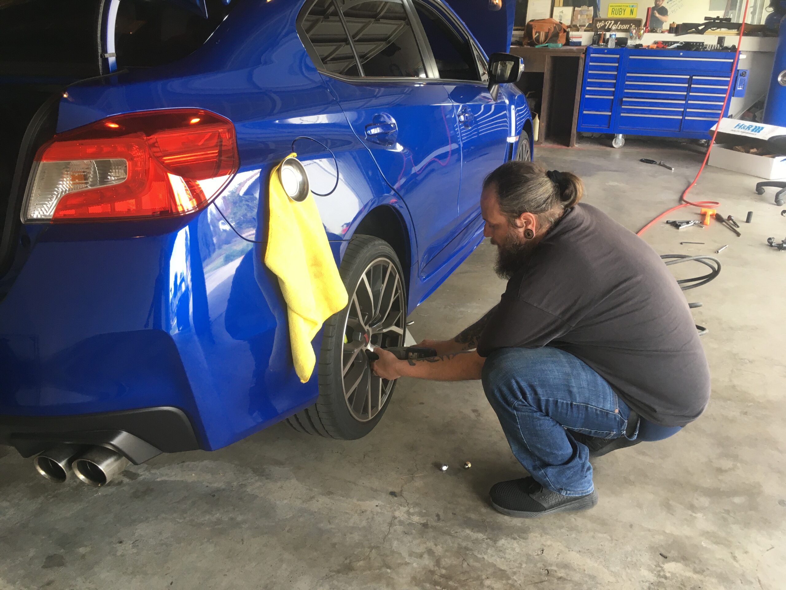
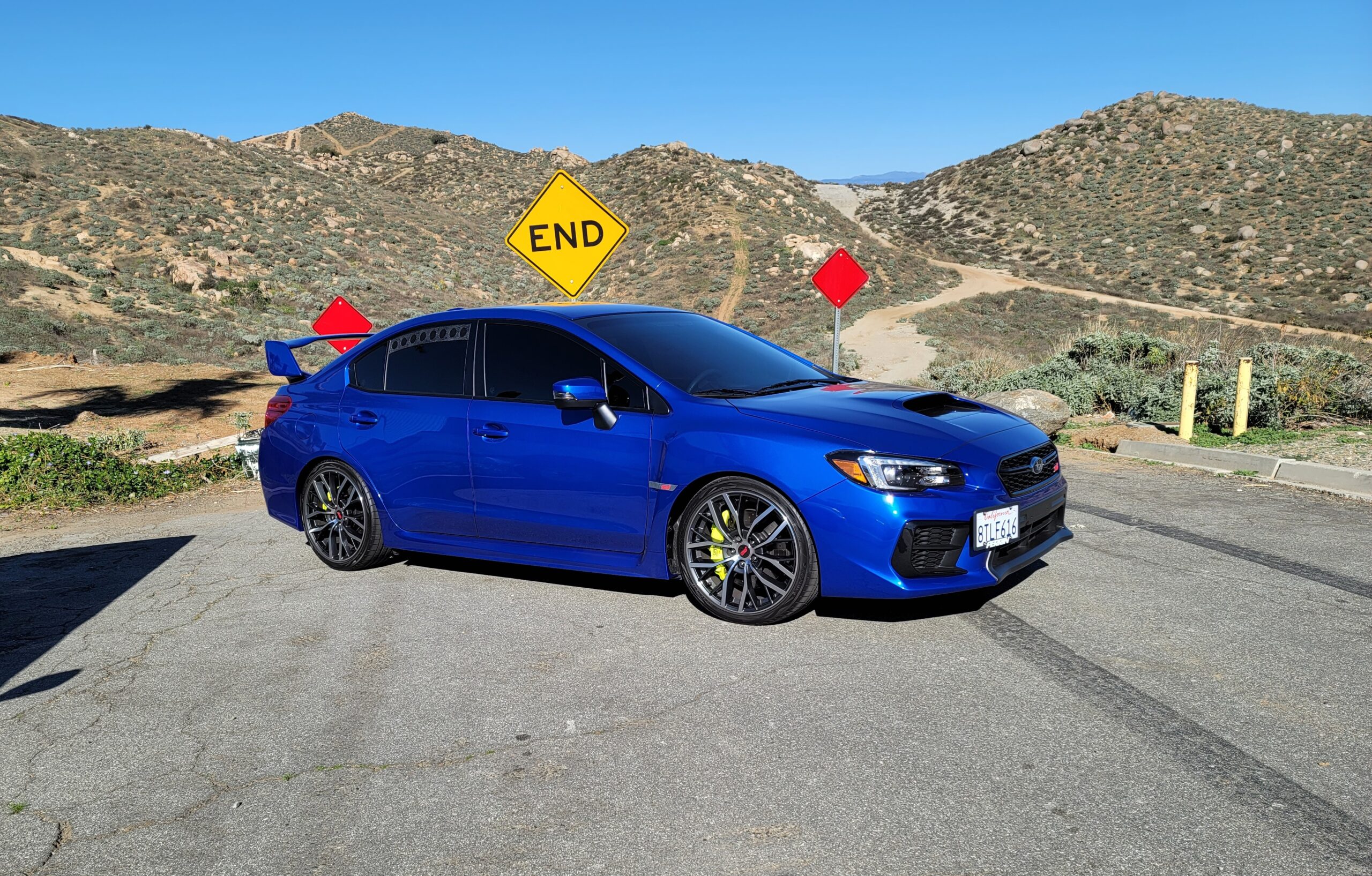
Before
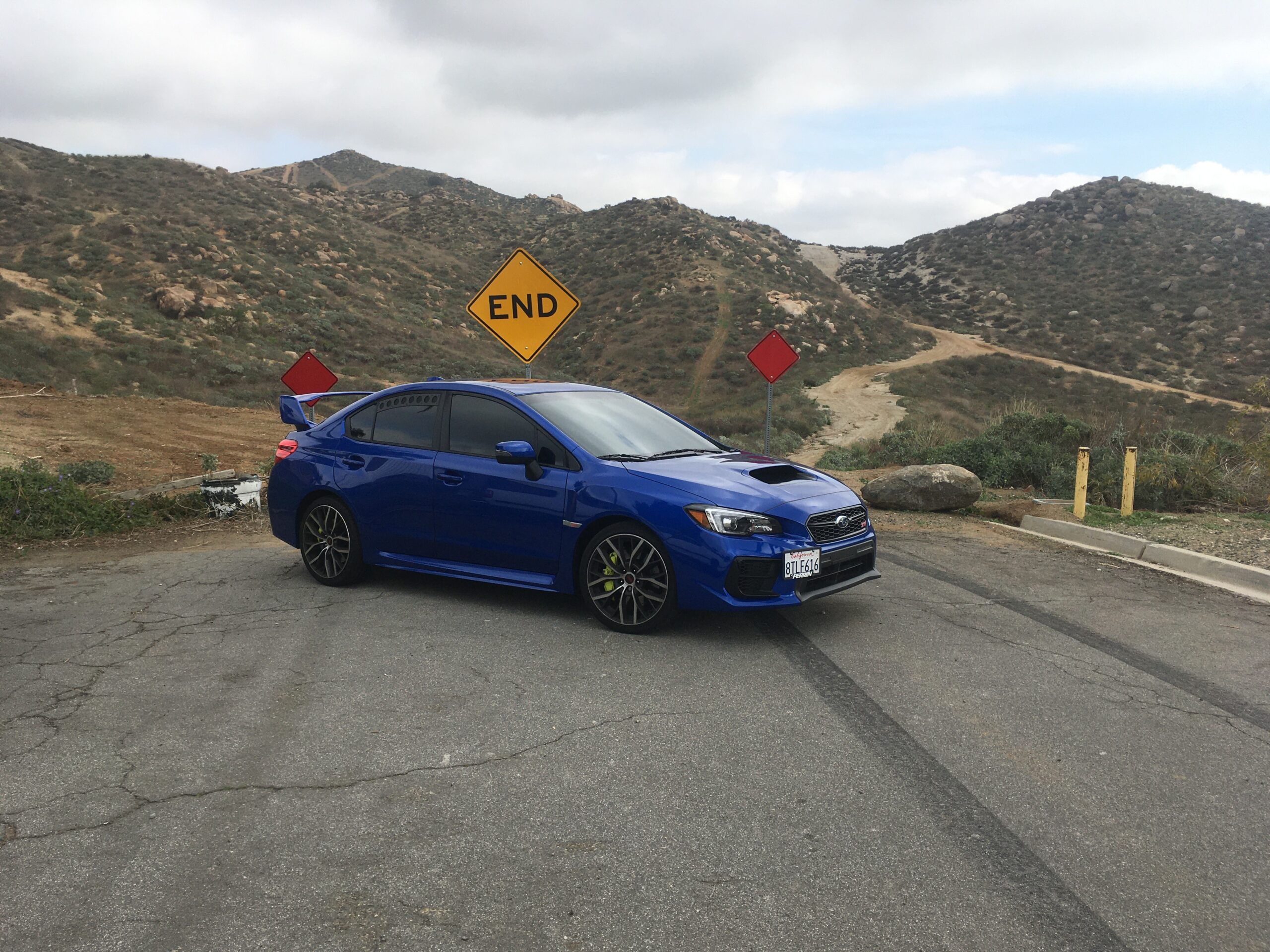
after
Special shout out to SubiSpeed, who we did research a bit before attacking this install, and also found their quick torque spec chart here.
You can also see our official review of the H&R lower springs here.


